Visette 2 VRi Info
February 2014

Just picked up two Visette 2 VRi HMDs that were in pretty bad shape. They needed major cleaning, new eyecups, re-sheathed cables, a new IPD motor in one unit, and panels near the microphone replaced because they were missing. I also used some clean air to blow a ton of dirt off the LCD panels. All of that is done on the first unit and its looking pretty good. I had to disassemble the first unit again when I received my IPD motors. Below is a quick teardown for those who are interested. Taking it apart also gave me a good excuse to trace down the pinouts.
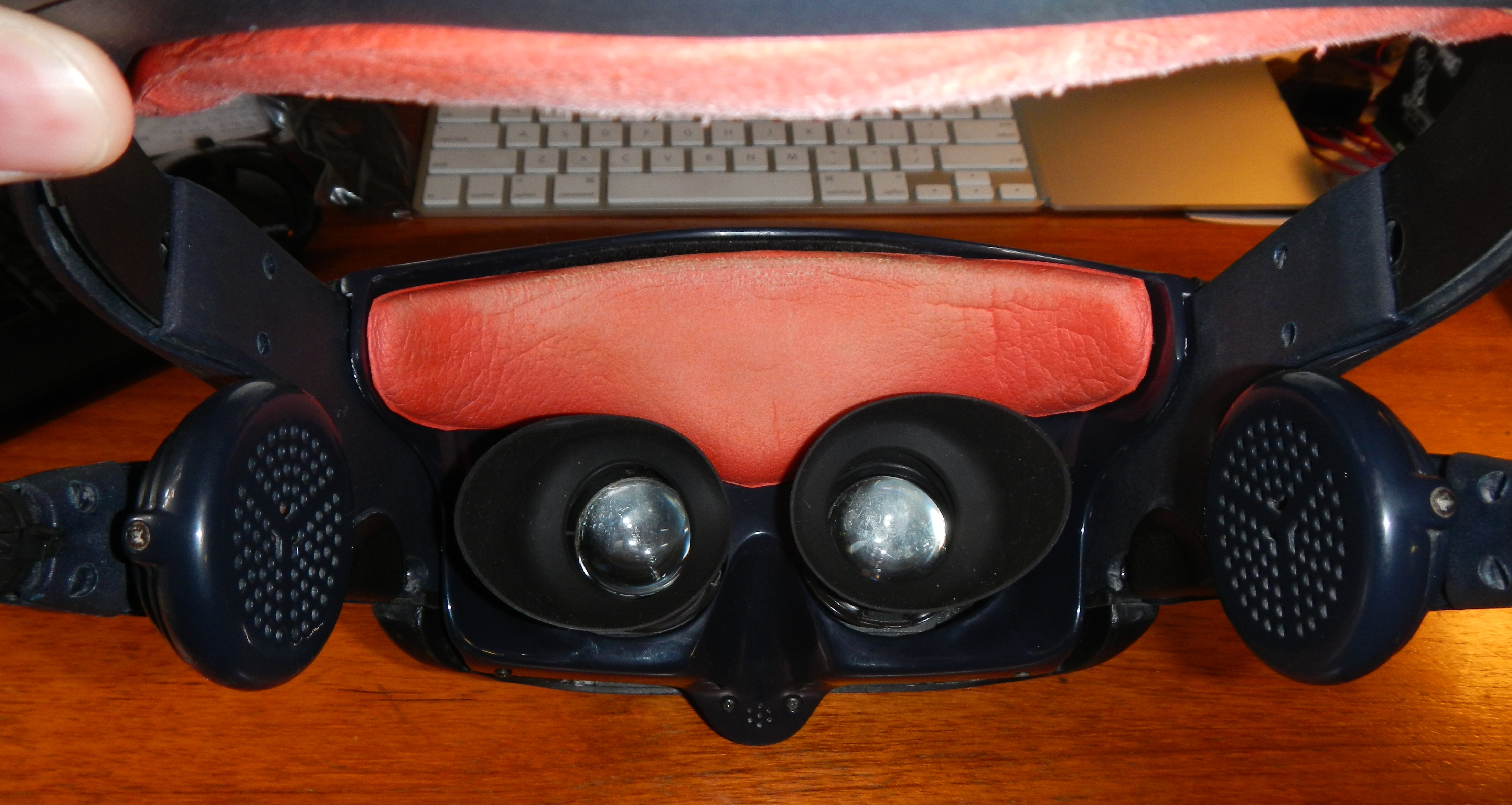
First you’ll need to remove the front forehead pad which is held in place via velcro. The red pad in the image below is the forehead pad. Be careful removing it as old velcro backing can lose much of its stickiness. You may need to replace the velcro if it’s too old.
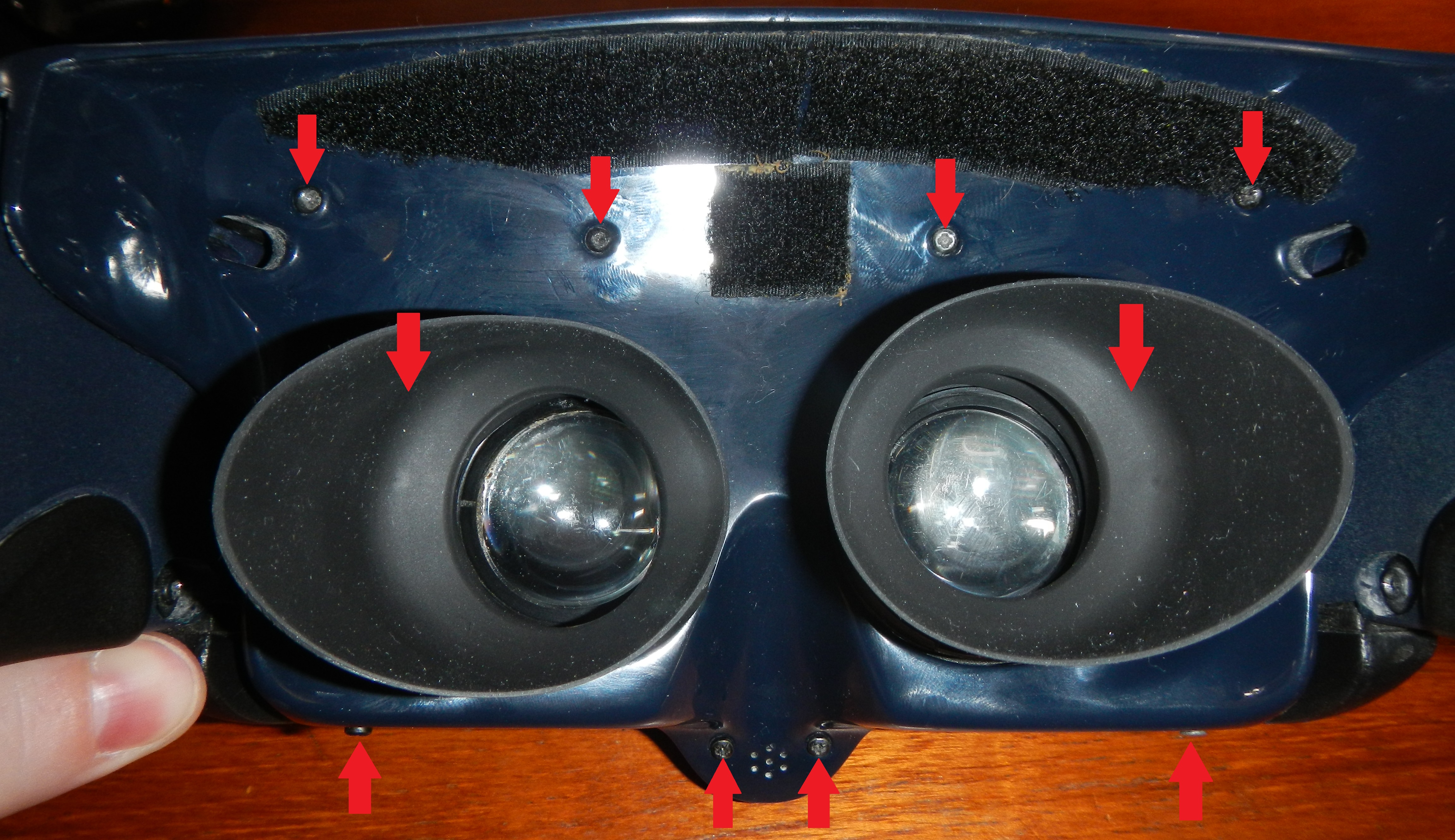
Then remove the screws marked in red to remove the front face mask of the HMD. You’ll also need to remove the eyecups by carefully un-snapping them. I replaced the original eyecups with PVS-14/PVS-7 rubber eyecups used for night vision googles (search Goggle). You’ll need to save the plastic retainer clips from the old rubber eyecups and use them to attach the new ones. It’s fairly simple to do but will require some cutting of the new eyecups to remove some material and hold the original retainers in place.
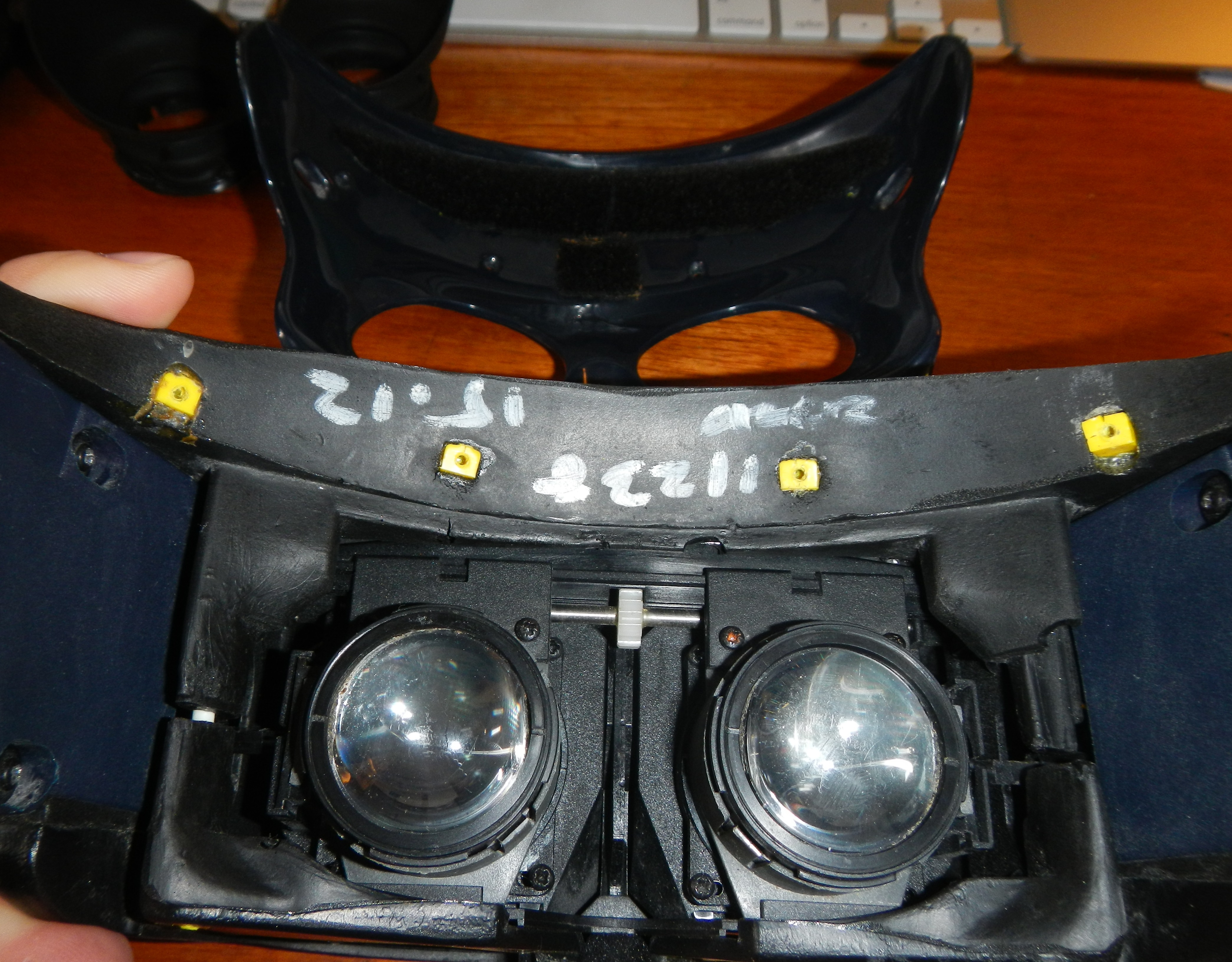
With the front face mask and eyecups removed you should see the optical assembly like shown below.
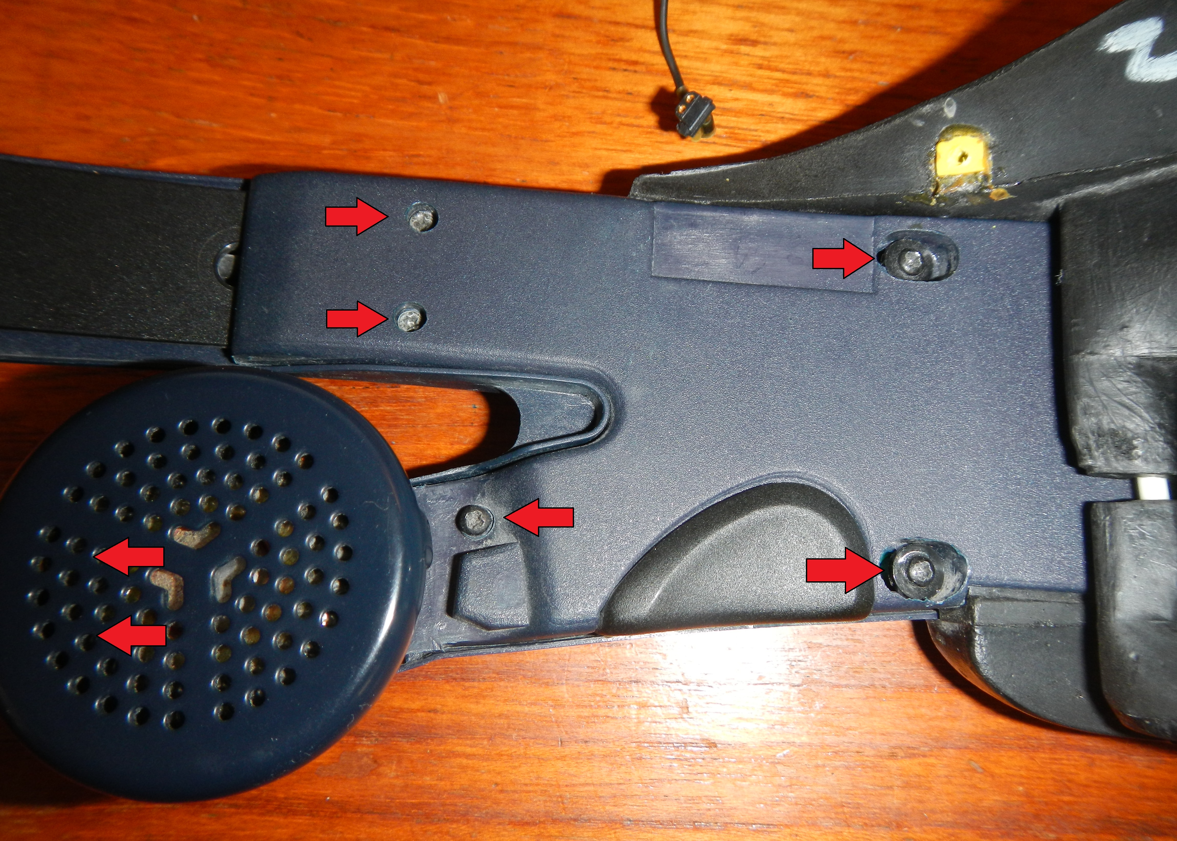
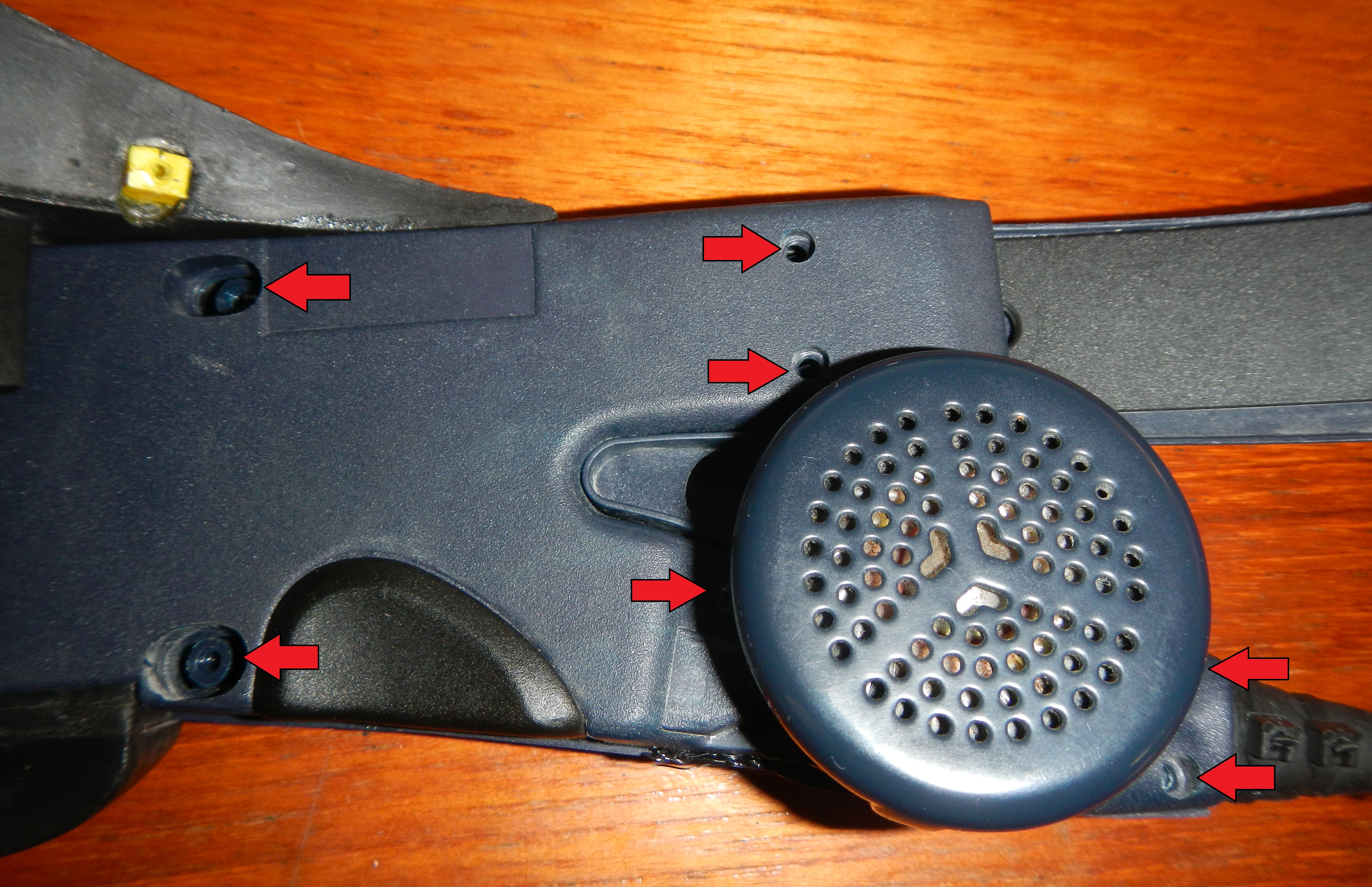
Now its time to remove the covers over the left and right temple PCBs. After these are removed you’ll be able to remove the main optical assembly with LCDs. Remove the left temple cover screws as indicated by red arrows below. There are two screws behind the headphones that can be seen if you rotate the speakers.
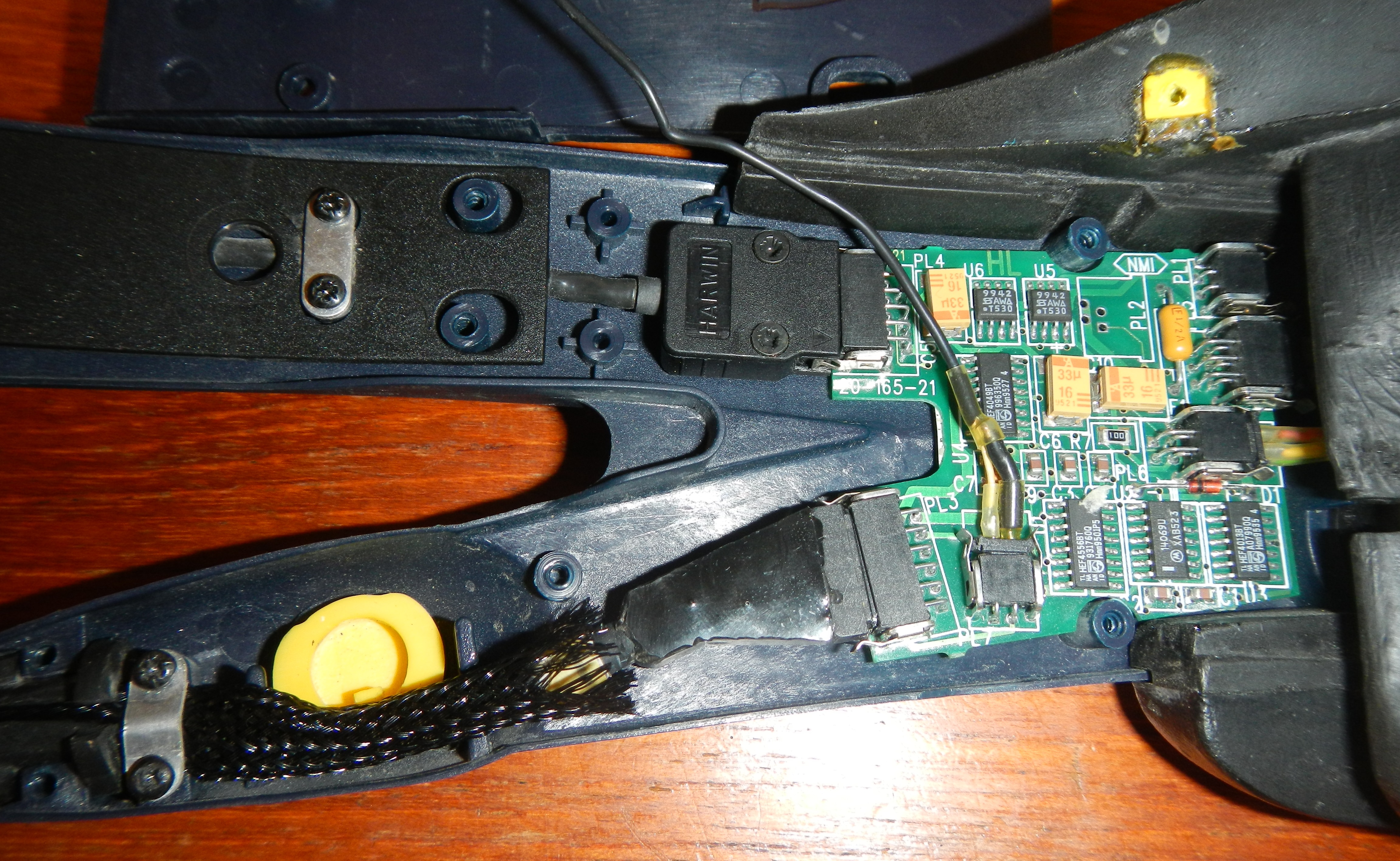
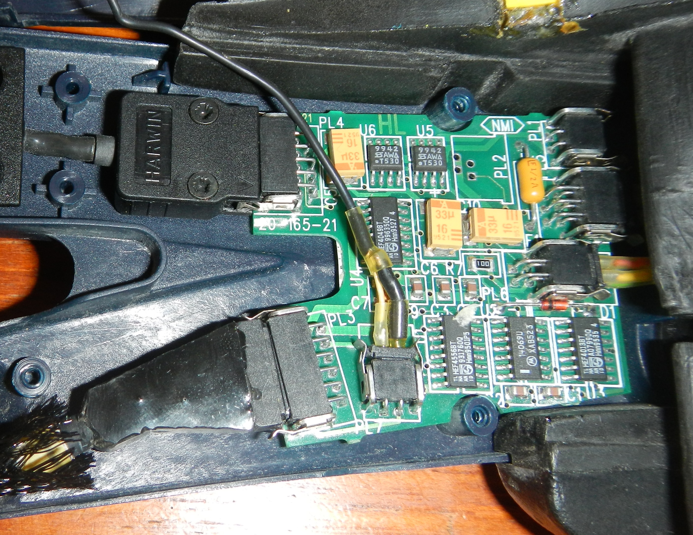
Once the cover is removed you’ll see the left temple PCB as shown below. I’ve already re-sheathed the cables as you can see in the image.
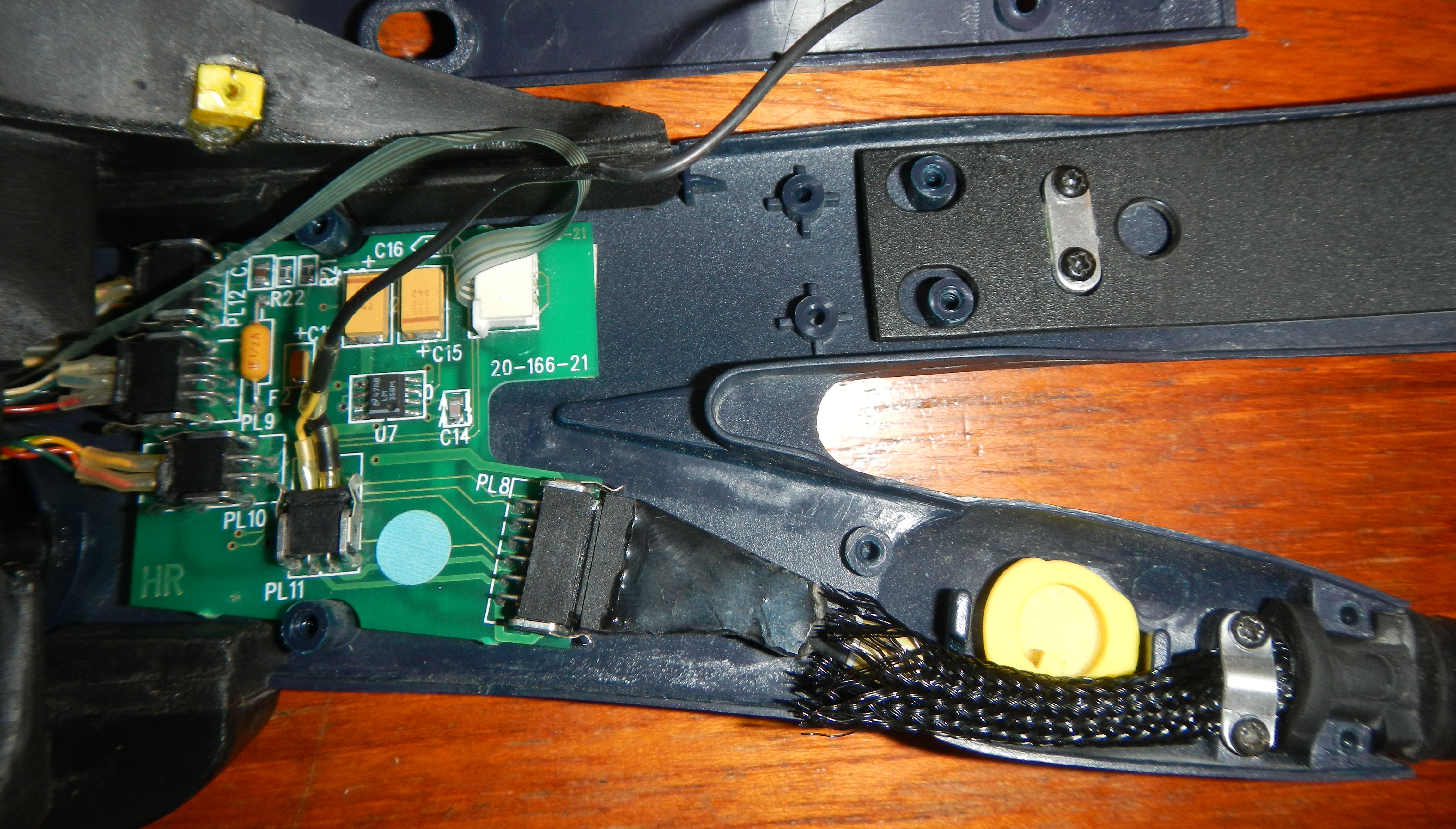
Now repeat for the right temple cover.
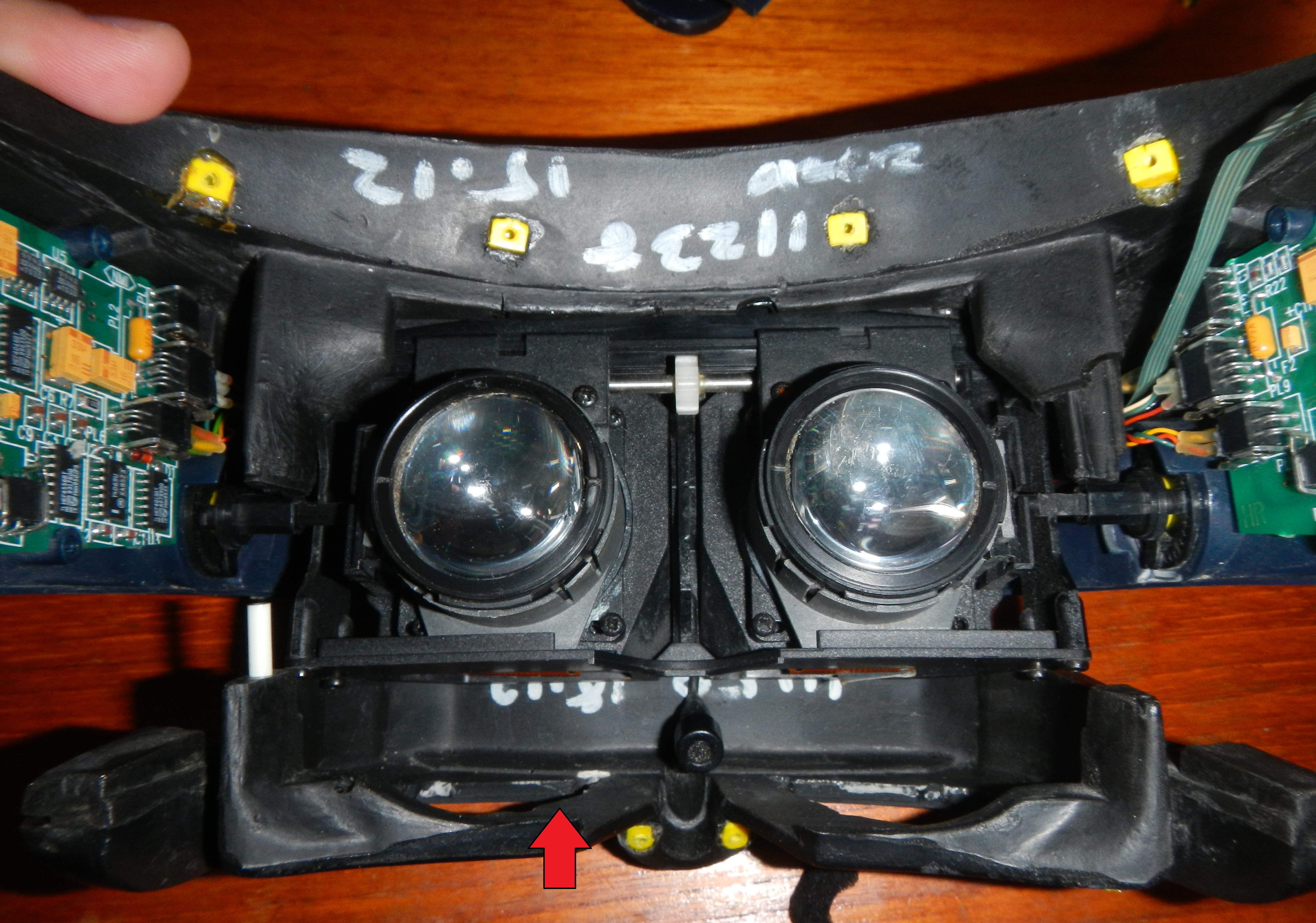
Now remove the bottom rubber insert of the Visette HMD as marked by the red arrow in the image below. The top rubber insert will come out in a similar fashion. They hold themselves in place by grooves in the rubber.
Now if you very carefully pull the arms of the HMD away from the eyepieces/LCDs the whole assembly will come loose from the HMD housing. The focus rods are really what is holding it in the housing along with the rubber inserts. See the red arrows below. You can then remove the upper rubber insert that holds the IPD buttons.
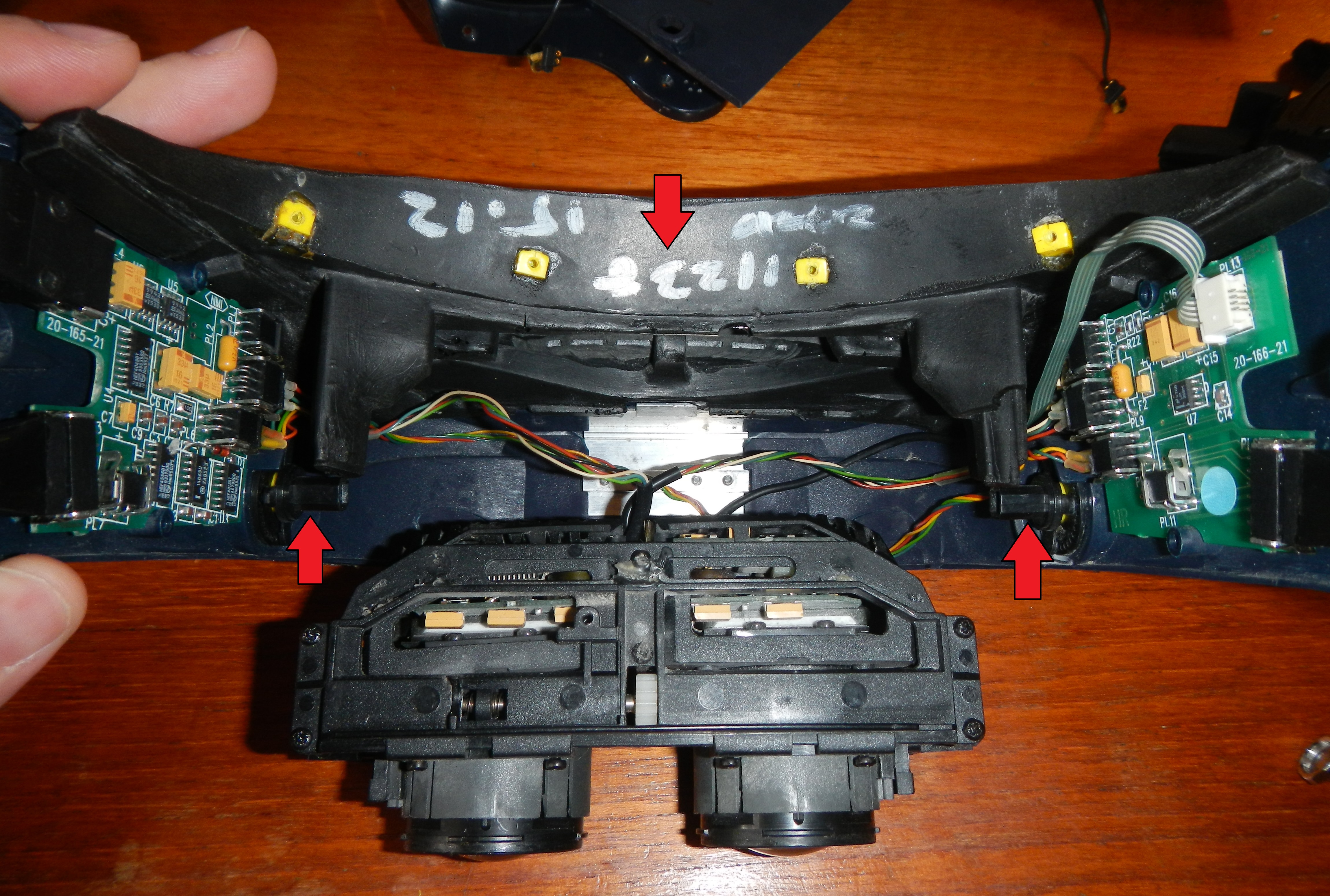
Now you have a disassembled Visette 2 VRi HMD. Go in reverse to re-assemble. The only thing to do is unplug all the cables if you need to. Be careful as they are fragile. Especially the flex cable going to the IPD buttons.
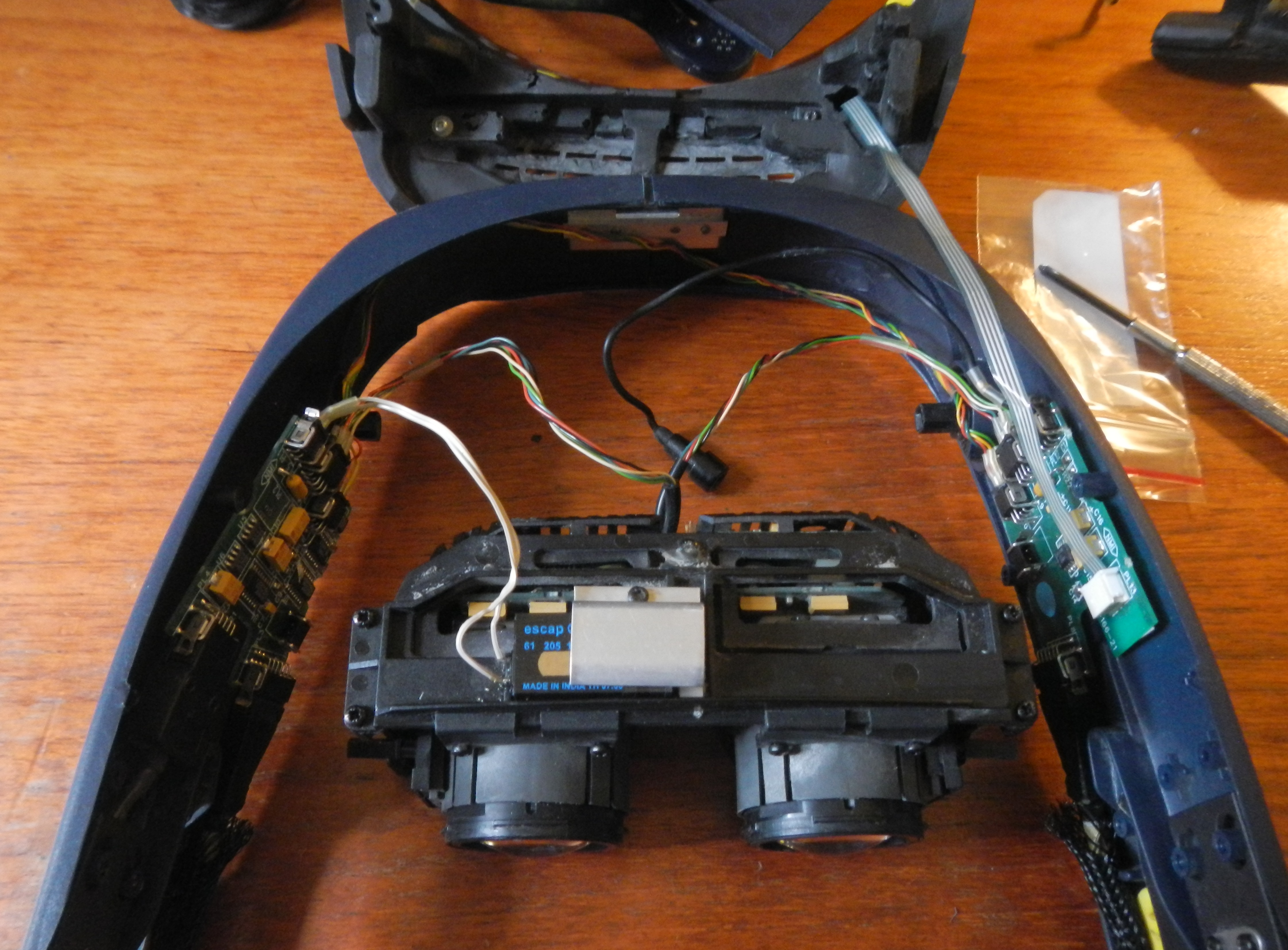
Boards and Pinouts
There are several boards in the Visette 2: left temple board, right temple board, and the LCD electronics. The main video chip in the Visette 2 for each LCD is the Sharp IR3Y06, similar to the IR3Y05 used in the VFX1 and CyberMaxx HMDs.
The IPD motor for the Visette 2 is the Escap M915L 61 205. Any Escap M915L 61 205 motor will work as the front reduction gear boxes are easily removed. I ordered the only Escap M915L motor I could find and used my old gear reduction boxes from the original motor. They are held to the main motor via 4 screws. Be careful when pulling them apart as there are small gears inside that are easily lost.
Here is the SU2000 technical manual which includes details on the Visette 2 HMD including pinouts. I also have a copy of the SU2000 user manual.
Below are the pinouts for the main connector (the Visette main connector to the MMD electronics box) as well as all the internal connections for the boards. Be aware that I’m numbering the pins as shown in the tables starting with PIN1. PIN1 is always marked with a square solder pad. The Visette technical manuals number them like old TTL logic chips. I’m numbering them more typical to connector pinouts.
Main Visette 2 VRi Connector Pinout
| Main Visette 2 NTSC Connector at MMD | |||
|---|---|---|---|
| Function | PIN # | PIN# | Function |
| Right Video In | 25 | 26 | Right Video GND |
| GND | 23 | 24 | Mic 9V |
| Mic #1 | 21 | 22 | GND |
| Left Backlight Enable | 19 | 20 | Right Backlight Enable |
| Right Audio+ | 17 | 18 | Right Audio- |
| Right 9V PWR | 15 | 16 | Right PWR GND |
| Left Shield | 13 | 14 | Right Shield |
| Left 9V PWR | 11 | 12 | Left PWR GND |
| Left Audio+ | 9 | 10 | Left Audio- |
| Tracker Coil 3 | 7 | 8 | Tracker Coil 3 |
| Tracker Coil 2 | 5 | 6 | Tracker Coil 2 |
| Tracker Coil 1 | 3 | 4 | Tracker Coil 1 |
| Left Video Input | 1 | 2 | Left Video GND |
The backlight enable lines are active low.
Left Temple Board Connector Pinouts
| PL1 | |||
|---|---|---|---|
| Function | Pin# | Pin# | Function |
| IPD Motor- | 1 | 2 | IPD Motor+ |
| PL3 | |||
|---|---|---|---|
| Function | Pin# | Pin# | Function |
| Left 9V PWR | 11 | 12 | Left PWR GND |
| Left Audio + | 9 | 10 | Left Audio – |
| Tracker Coil 3 | 7 | 9 | Tracker Coil 3 |
| Tracker Coil 2 | 5 | 6 | Tracker Coil 2 |
| Tracker Coil 1 | 3 | 4 | Tracker Coil 1 |
| Left Video Input | 1 | 2 | Left Video GND |
| PL4 | |||
|---|---|---|---|
| Function | Pin# | Pin# | Function |
| N.C. | 9 | 10 | N.C. |
| Tracker Coil 3 | 7 | 9 | Tracker Coil 3 |
| Tracker Coil 2 | 5 | 6 | Tracker Coil 2 |
| Tracker Coil 1 | 3 | 4 | Tracker Coil 1 |
| Tracker GND | 1 | 2 | Tracker Shield |
| PL5 | |||
|---|---|---|---|
| Function | Pin# | Pin# | Function |
| Left Video Input | 5 | 6 | Left Video GND |
| Left Backlight Enable | 3 | 4 | N.C. |
| Left 9V PWR | 1 | 2 | Left PWR GND |
| PL6 | |||
|---|---|---|---|
| Function | Pin# | Pin# | Function |
| IPD SW2 | 3 | 4 | GND |
| IPD SW1 | 1 | 2 | Left Backlight Enable |
| PL7 | |||
|---|---|---|---|
| Function | Pin# | Pin# | Function |
| Left Audio #1 | 1 | 2 | Left Audio #2 |
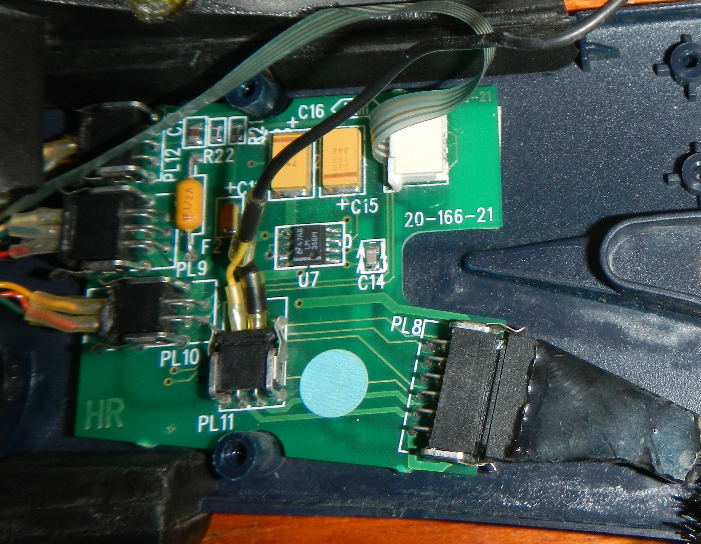
Right Temple Board Connector Pinouts
| PL8 | |||
|---|---|---|---|
| Function | Pin# | Pin# | Function |
| Right 9V PWR | 11 | 12 | Right PWR GND |
| Right Audio+ | 9 | 10 | Right Audio- |
| Left Backlight Enable | 7 | 9 | Right Backlight Enable |
| Mic #1 | 5 | 6 | GND |
| GND | 3 | 4 | Mic 9V |
| Right Video Input | 1 | 2 | Right Video GND |
| PL9 | |||
|---|---|---|---|
| Function | Pin# | Pin# | Function |
| Right Video Input | 5 | 6 | Right Video GND |
| Right Backlight Enable | 3 | 4 | NC |
| Right 9V PWR | 1 | 2 | Right PWR GND |
| PL10 | |||
|---|---|---|---|
| Function | Pin# | Pin# | Function |
| IPD SW2 | 3 | 4 | GND |
| IPD SW1 | 1 | 2 | Left Backlight Enable |
| PL11 | |||
|---|---|---|---|
| Function | Pin# | Pin# | Function |
| Right Audio+ | 1 | 2 | Right Audio- |
| PL12 | |||
|---|---|---|---|
| Function | Pin# | Pin# | Function |
| N.C. | 1 | 2 | 9V |
| GND | 3 |
| PL13 | |||
|---|---|---|---|
| Function | Pin# | Pin# | Function |
| IPD SW1 | 1 | 2 | IPD SW1 GND |
| IPD SW2 | 3 | 4 | IPD SW2 GND |
 Mellott's VR