 Mellott's VR
Wireless Glove Project
May 2000
Well this project is finally complete. I’ve learned more then I could of hoped from all of this. I started this project over a year ago. First it started out with just brainstorming and research. After I got the proper test equipment, I would say I spent a few months of free time, after work, on the glove. Improvement and redesigning the concept. I started with an entirely analog system. That was a mistake. Then I went digital but the circuits were still to space consuming. Finally when I got my act together I went with a ATmega163 microcontroller. Cheaper overall, less space consuming, and easier to work with. This project is a little different then the others. It not so much a step by step but more of an overview. The amount of depth that I would have to go into would take up a huge amount of time. I will add more as time permits but if you need any details let me know.

Excluding the equipment costs, this project will cost approx. 100 to 150 dollars. Without equipment, unless your just doing it for the challenge, I would not recommend this project for most people. The programmer for the microcontroller was 100 dollars with a 250 dollar O’scope, and a variety of tools stacked on top of that. One thing I will do, if you really want to do this project, is burn the chips for you. Send me the money or a chip and I’ll burn one for you and send it out as fast as possible. That will keep your cost down. You will definitely need an O’scope for troubleshooting and repair. Otherwise, it will be cheaper and easier to buy a 5DT glove for around 495 dollars.

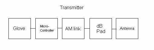
I’m going to give you a basic run down of the operation of this glove. In its simplest form, what we have here is a wireless A to D converter. Lets start with the transmitter section. On the AtoD pins, the microcontroller reads the values of the voltage dividers determined by the position of your fingers. The internal program constantly loops and reads these values. It then converts them to digital and sends them out the on board UART. The data is send out at a 4800,n,8,1 format. Which means a port speed of 4800, 8 data bits, and 1 stop bit. Finally the UART pin feeds to an AM modulated link which is transferred to radio waves. Other then the microcontroller and the AM link: there is a voltage regulator, voltage divider for the glove, a 4 MHz crystal for the microcontroller, a 3 dB pad for matching, and the antenna.
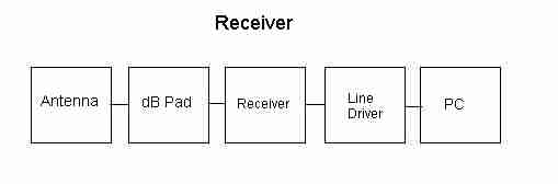
In the receiver the AM link picks up the radio waves and converts them back to a digital format. The receiver feeds this data to a Max232 line driver. This line driver converts the 0 to 5V signal to a +12 to -12 RS-232 format. That is then feed to one of your COM ports. The other components in the receiver are: an antenna, a 3 dB pad, and a voltage regulator. So as you can see this project doesnt consist of much component wise. But the amount of time to generate the glove is consuming. The fun is making it all work together.
This project is to show that it is possible to produce homebrew VR equipment. And I display it here for anyone who wants to give it a go. With the test equipment I’ve purchased initially I can now produce a variety of other VR projects. So enough talking lets start with what you’ll need.
You will need:
- The hand portion of a power glove or five resistive flex sensors.
- Approx everything in this material list.
- Desktop PC with Com2 serial port.
- ATI programmer-STK500.
- Oscope.
- Soldering Iron
- Dremel with attachments.
- Hack saw and vise (PCB design).
- Hell of a lot of time!!!!
I recommend building the unit on a breadboard before putting it together on your PCB boards. It may save you a lot of time in troubleshooting and will also get you familiar with to breadboard or wire wrapped boards. The PCB’s can take some time to make. Otherwise, the first step is to build your the operation of the unit. The unexperienced my want to stickcustom PCB boards. This will take some time.
 The first thing to do is take a piece of paper and fold it in half. The top half will be the top of your PCB and the bottom will be the bottom of the PCB. Take your enclosure and place it on top of the top section and trace it. Now flip over the enclosure and make note of the holes you’ll have to drill and make note of them on your traced box. Basically you want your traced picture to look exactly like the inside of your enclosure where the PCB will be mounted. This will give you a template to draw your PCB layout.
The receiver side will be the same process except you will have a back side. With the receiver you want to take your drawing and fold it in half so you can hold it up to a light to see through the drawing. This way you can see where your traces are relative to the front. I started with placing the Vcc and Ground traces around the board. This may or may not be the correct thing to do as far as PCB design, but that’s what I choose to do. Then I placed all my components with respect to those traces. You have to of course take into effect where outside components will be entering the box.
Here are some pictures of my rough PCB’s with the components installed. I wish I could provide better pictures but this is all I have access to at this time. You can use this as your guide along with the schematics ( just email me) to place your components. I recommend using a 40 pin socket instead of soldering the IC directly to the PCB like I did. Also make sure all your holes are drilled in your enclosure before you stuff your boards. This will prevent any damage from happening to your boards (trust me, I know).

On the transmitter PCB I have included a 6 pin header to update the firmware in the system. I have also included a 3 pin header that is connected to the microcontroller. This 3 pin header is for the future x,y,z tracking cordinates. Its unclear but you can just make them out. I have grounded the 3 pin header until further use. This keeps the data in the lower program easier to look at.

One thing you may wish to do, that I didn’t, is to place test points on the PCB’s. A few that I would recommend are: the microprocessor out (pin 15), the receiver out, and the MAX232 line driver out. These points will be useful in your troubleshooting and signal conditioning if needed.
You may notice I may have a few extra components in my PCB pictures ( if you can see them. haha) then in the material list or in the schematic. You can see a rough copy of the schematics below. (If you save the pictures to your desktop then you can zoom in at a more detailed schematic.)

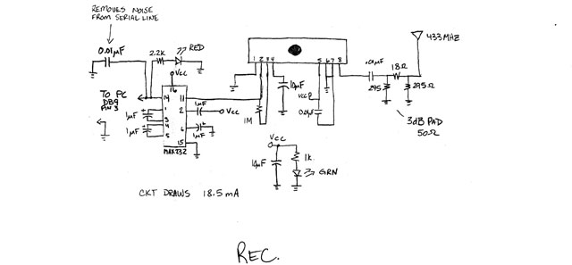
This is why I had packs of extra components in the material list. You may have to add caps and or resistors to help the circuit with signal conditioning. This will depend highly on the quality and layout of your PCB. This is where your electronics experience will play a crucial role. The receiver picked up a lot more noise when I placed it in the enclosure compared to the breadboard. So I had to place additional caps between Vcc and Gnd and a few other key points, like the line driver. Its still not as stable as when it was mounted on a breadboard. Thats due to my limited experience on circuit design. Experiment with the circuit somewhat and see what works the best.
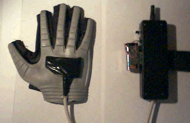
As for the hand portion of the glove, I placed a PCB board where the old ultrasonic electronics was mounted. Instead of soldering directly to the flex sensors themselves I used a PCB board. The board is mounted to the glove and the flex sensors are soldered to them. Then my cable, to the bulk of the electronics, is mounted to the board. The PCB is just a straight through connection. This relieves the stress of movement off of the flex sensors so that they won’t be damaged over a period of time. Its much easier to replace the cable then the flex sensors inside the glove. I then wrapped the board in electrical tape just to hide the wires. It’s not the neatest way to go but it works. I also zip tied the cable to the glove through two slits in the material. This holds the cable down and prevents it from pulling on the wires. Also note that the PCB on the hand portion of the glove will pick up RF noise from near by sources like your monitor and or computer. I didn’t shield it directly but the electrical tape alone helped some what. But as we electronic guys go, it should be shielded.
A little on the enclosures. On the transmitter side you will have to drill a hole for the antenna, one for the cable from the glove, two for the LED’s, and another one for the switch. I notched the enclosure to take my SPST switch. The LED holders will need a 1/4 hole and the cable hole will depend on the type you use. I used a 3/8 hole. You will also need to drill a small hole for the 9V battery snap on. The antenna hole is approx a 3/8 hole. The battery clip seen in the picture was attached with a self tapping screw. As far as the arm strap, I notched the enclosure on both sides to accommodate the size of the arm strap. I used the strap from a duffle bag. Velcro straps would be nicer.

The receiver will need six holes drilled. One for the antenna, two LED 1/4 holes, a cable hole, a hole for the toggle switch, and a final hole for the power jack. The cable hole is 3/8 and the toggle switch I used is a 1/4 hole. The hole for the antenna will depend on the one your purchase. The unit from RFDigital.com is about a 3/8 hole. The power jack hole will also depend on the type purchased. I had to shave the enclosure to get the power jack to fit because it was really small. The enclosure was too thick. This is where your Dremel with those grinding attachments will come in handy. Just use common sense. One option, that I wish I would have done, was to put a serial port connection on the enclosure instead of attaching a cable. Then you can use any old serial cable that you have laying around.
When the PCB’s are complete and the boards are stuffed. Mount everything and attach the switches and LED’s. Keep your holes for the antennas a little tight. Then use a zip tie around the base of the antenna to keep it secure. If you can configure your PCB to attach the antenna directly to the board, that’s the way it was designed to be used. When you power on the unit, TRX and RCX, the Red power LED’s should come on first. Then the Green data LED’s should light shortly after. This is a visual indication that the unit is operating properly. On initial power up I would leave the enclosures open and do a bench test. More then likely you’ll have to adjust or check something. Unless your just that good.
The only thing left is to put together all the pieces. After the boards are mounted and the holes are made for the cables. Run your cables in to the enclosures and attach them. You should attach the LED’s, switches, and antenna’s at about the same time you mount your boards. Then place zip ties on the inside of the enclosures on the cables to prevent them from pulling loose. Put the tops on and your ready for some data testing.
Once your circuit is operational hook it up to the serial port and a terminal program to see if data is being received on your port. It will be transmitted in HEX$ format. So make sure your terminal program can read Hex. You should be able to see a format of 80 0 X X X X X 0 0 0. The first two bytes are for syncing and the last three are for the x,y,z coordinates that will be added in a later project. The X’s are the finger flexure data. This data, depending on the resistors you chose as the flex sensor counterparts, should be between 0 and 255. 255 being completely unflexed and 0 being bent over like crazy. Normal operation you should see data between approx 70 to 255. If you get data at 255 that doesn’t respond while your moving your fingers, then the voltage going to the microprocessor is above 2.5 V. You need to change the resistors in the voltage divider to get a little under 2.5V when your hand is flat. These corresponding resistors will vary from unit to unit and some experimentation will be required. Typically you want the resistors to be slightly less resistive then the flex sensor when flat. This will give you the correct voltages. You can see in the schematic the values I have chosen.
For this particular project I added a fifth flex sensor in the pinky of the power glove. For software purposes I tied this finger to the ring finger because when I inserted the sensor it was folded over. So the response is somewhat non-linear. It’s never the less available for use. Whether you want to use it or not is up to you.

Here is a test program I wrote in VB6 for the glove. Sorry about the really terrible picture. It displays formatted data in decimal format and also displays a rough hand model the mimics your hand movements. The program uses Com2 as the serial port. It is not extremely fast so some lag is noticeable. This comes from the way I read and sort data read from the serial port. Keep in mind this is only a test program and if you want to use the glove for anything other then this, you will have to write your own software. The glove will also work in QBasic with a similar program to that of the glove built in the DataGlove Project. Basically the glove will operate with any system that can read data from a serial port. The glove continues to send data to the PC as soon as its on. The data stream is continuous.
If you notice that the hand model is glitching a lot, then you need to adjust the receiver on your PCB. It’s out of tune. One thing might be to drill a hole in your enclosure to adjust the receiver from the outside. You need to adjust the inductor on the receiver for the best signal. The best way to do this is with your Oscope connected to the signal out of the MAX232 line driver while adjusting the inductor for the cleanest signal.
The wireless glove does work rather well. The link is pretty stable. I would recommend a FM link though if possible. The AM link used in this glove appears to be sensitive to temperature. It has a range of approx 20 feet, depending on any RF noise in the room. It will operate, if its in the same room ,but degrades with increased distance. The glove operates best when the receiving station is higher then the transmitter. I didn’t use any type of shielding in the receiver. Addition of shielding may improve the operation. The transmitter didn’t seem to improve the link with shielding but the receiver did drastically. The glove looses connection occasionally but the test software is written to recover from this condition rather well. A better link would make this glove a robust product. It does serve its purpose though, as far as homebrew is concerned.
Well I know this is kind of a rough, quick run down of the project but it should get your started. If you have any question please email me. I have ENORMOUS amounts of information on this project. I have spent countless hours on it, so don’t hesitate. So on with the next project and good luck!!!!
Here is the program that is burned into the ATmega163 chip.
