 Mellott's VR
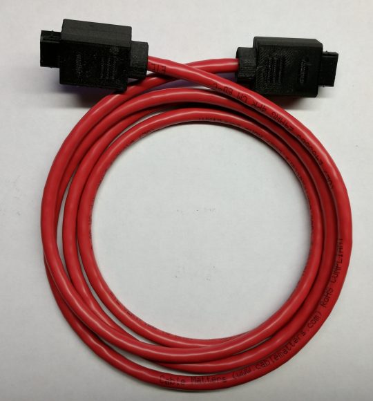
Virtual Boy Wired Link Cable Build
11/12/2017
I’ve been building wired link cables for Nintendo Virtual Boy for a few months now. This is a cable to join two Virtual Boy’s together for 2 player games through the link port or game port. There are only a few games that use this functionality and none of them were original system releases. Hyper Fighting, TicTacToe, 3D BattleSnake, and a patched Mario Tennis game can use the link port to enable 2 player functionality. All of them are considered homebrews because even though Mario Tennis had some hidden 2 player code in it, you can’t enable it without a patch and a custom cartridge or a Flashboy.
I designed and built a professional looking cable to create the link cable that Nintendo never released. Here I’m going to give a how-to as a reference for the cables out there that I have built. You can use this to build your own cables as well but you’ll need housings and connector ends to build the exact one I describe here. If you’re looking for connector parts you can send me a message via my contact page.
First thing to know is that you’ll need some basic tools otherwise it makes things much harder. You’ll need needle nose pliers, 2 sets of tweezers (1 blunt strong set and 1 fine tipped set), sharp knife, 50mL epoxy gun, epoxy mixing nozzles, 3M DP-100 epoxy or similar, and 10cc syringes with dispensing tips. You can probably get away with not using the 50mL dispensing gun, 3M epoxy, and syringes if you use some Gorilla Glue or similar. If you’re only building one that’s probably fine. If you built 75 like I did, then you need something that is a bit easier to use and faster to dispense. Also keep in mind that this process takes me 65 minutes and I’ve built quite a few. Probably best to set aside a few hours just in case. In addition to tools and time you’ll need some parts to build the actual cable:
1. Connector housings and centers (Custom design and 3D printed in Onyx Carbon Fiber)
2. USB pins from USB connectors (Digikey 1175-1265-ND)
3. Small zip ties (JT&T 4″ Nylon Wire Tie PN: 4701-2M)
4. Red CAT6 cable
5. 1/16″ black heat shrink
6. Loctite 401
7. Rubbing alcohol and cleaning pads
If you want the 50mL 3M Epoxy, 50mL gun, syringes, and dispensing needles then you also need:
1. 50mL Dispensing gun
2. 50mL mixing nozzles
3. 3M DP-100 Epoxy
4. 10cc Syringes
5. 20 gauge x 1″ Dispensing needles
Preparing Connector Covers and Center
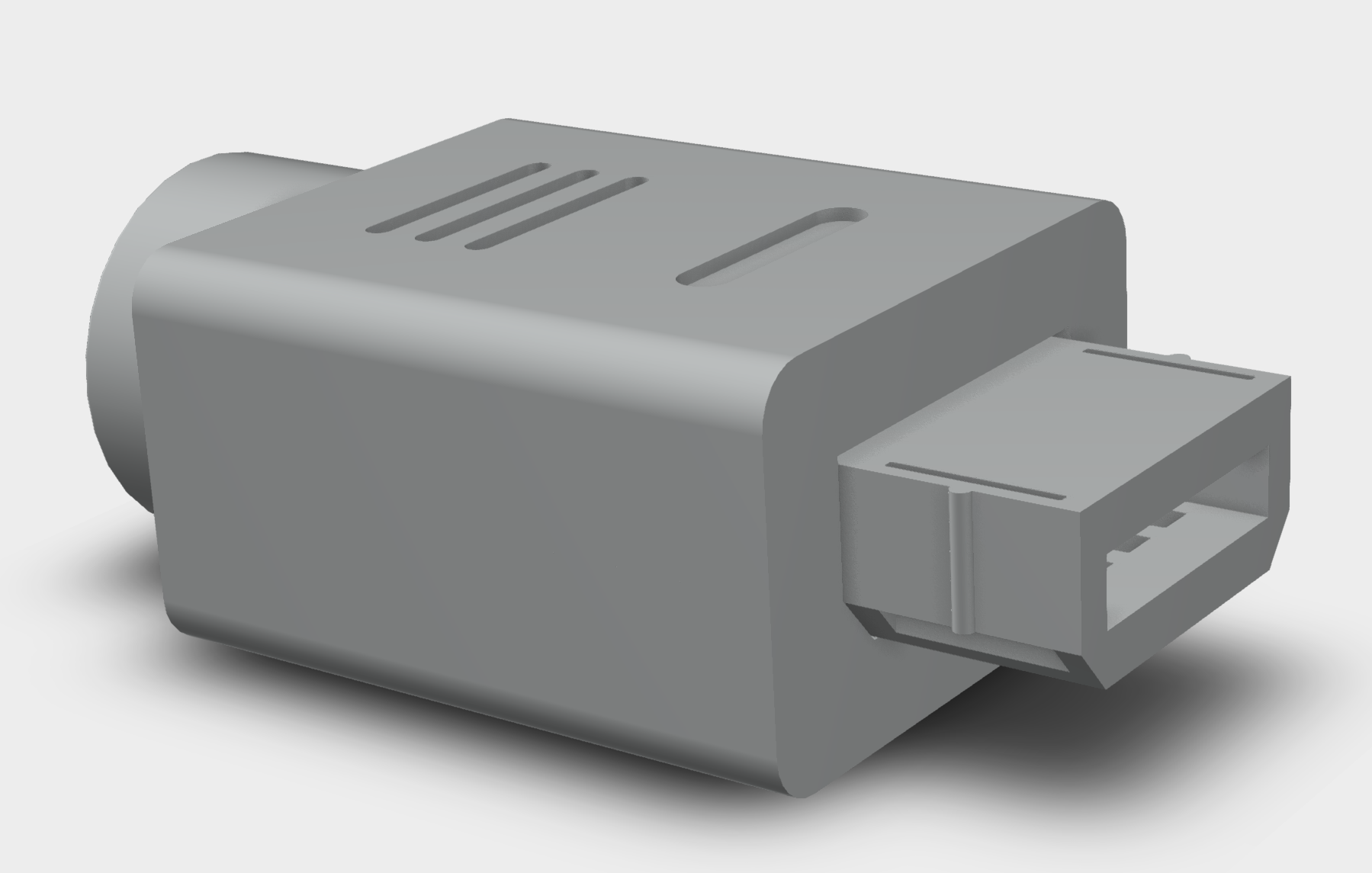
The connectors you’ll need are custom designed and will need to be of your own design or purchased from me. These connectors were a several month effort to develop. The link port on the bottom of the Virtual Boy was used as a guide line as well as the VB controller connector and housing. The design that ended up being used in the cable builds is revision 5. They’re 3D printed using Onyx, a carbon fiber black material from Markforged. They need to be printed in a specific orientation to come out with smooth finishes on the outsides of the covers and center. This will make them look very professionally done. And the material is super tough.
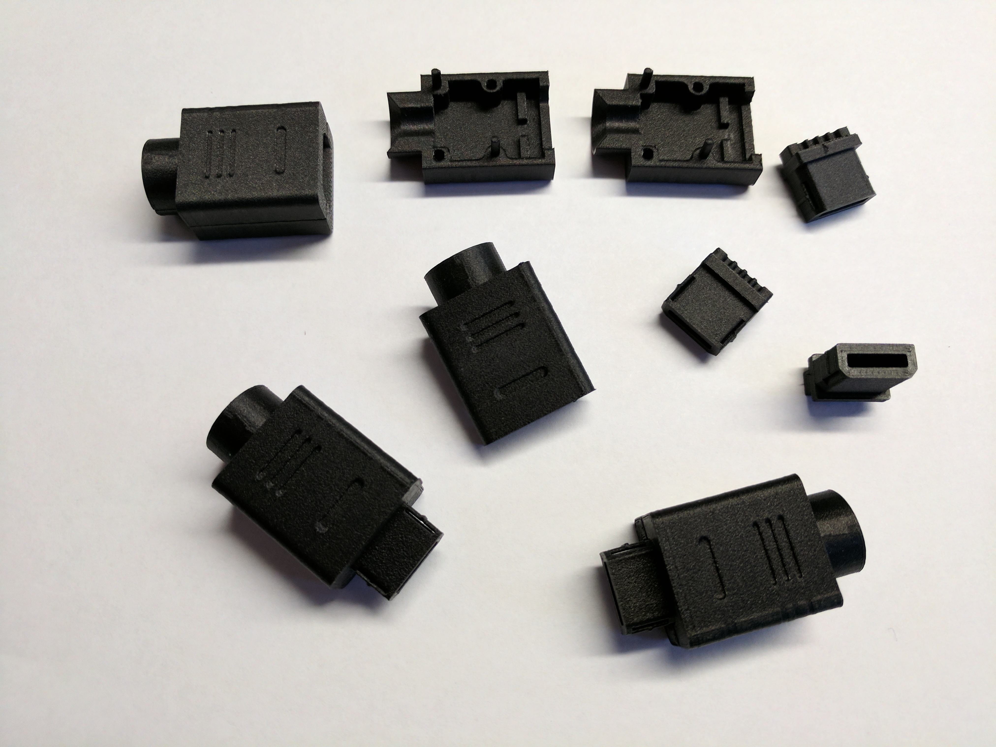
The connectors come in three pieces. Two cover pieces and a center. The covers are not symmetric and one of them has a bevel where the center piece goes. This will make sense once you look at the parts. Be sure to do this before hand because once you get the glue in place its near impossible to get back apart.
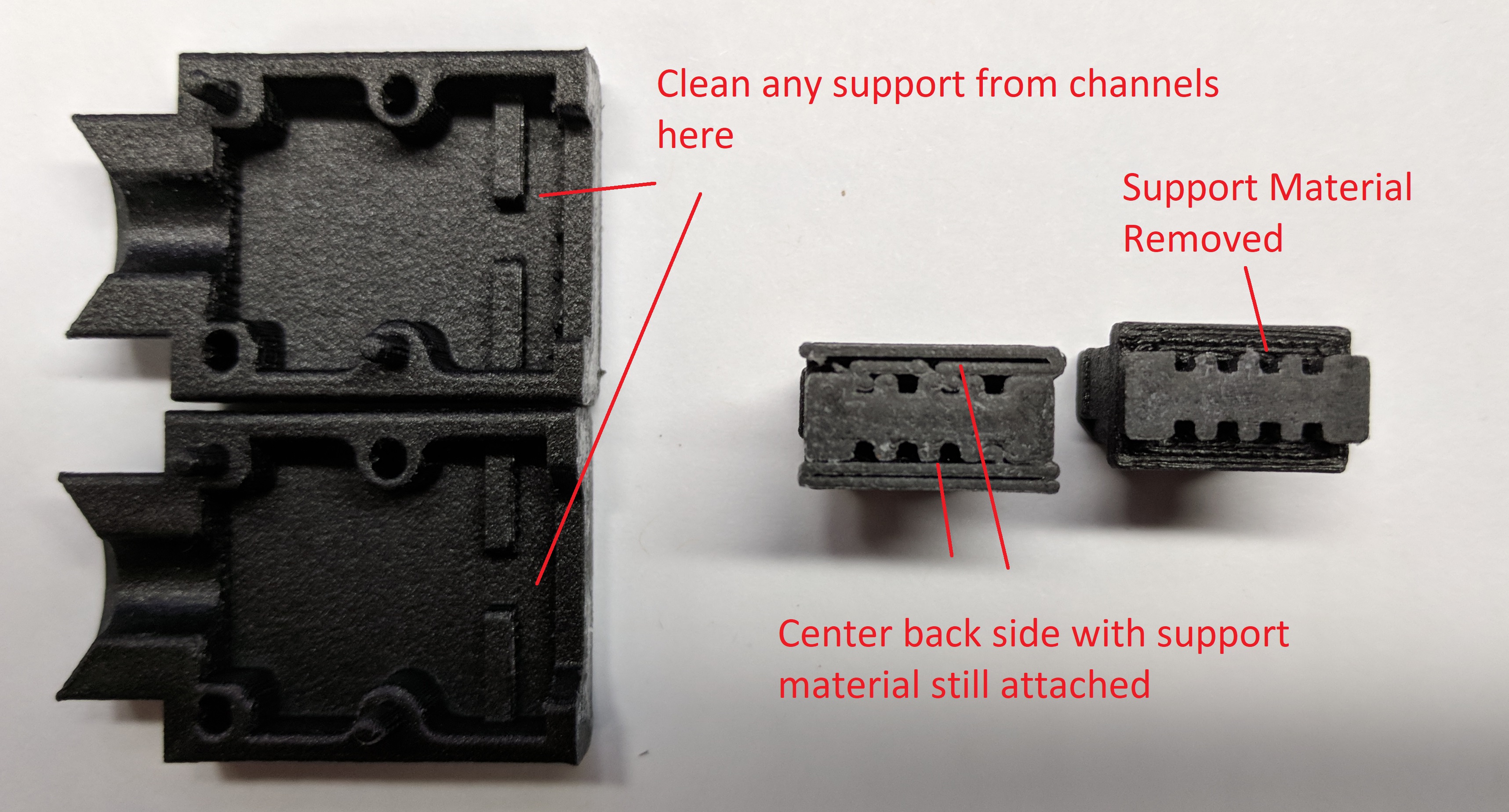
There may be some support material left over in the inside of the covers as well as in the pin slots of the center piece. Make sure to clean this all out and take a careful look over the connector parts. You’ll need two connector sets for a cable. The basic idea here is do a fit check and make sure your parts all fit together correctly and that the slots where the USB pins will be inserted are clear of any extra material that shouldn’t be there. You can use a strong pair of tweezers to remove the support material that may be in the cover channels and on the back of the center piece, as well as the support material on the back of the center piece. See pic below. There may also be some white residue on the cover top faces. Clean this off with alcohol. This is sticky glue used when 3D printing to adhere the part to the print bed.
Extracting USB Pins
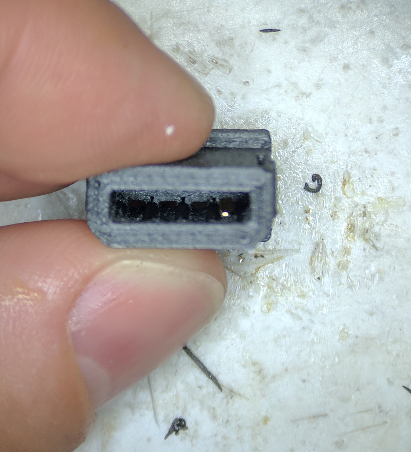
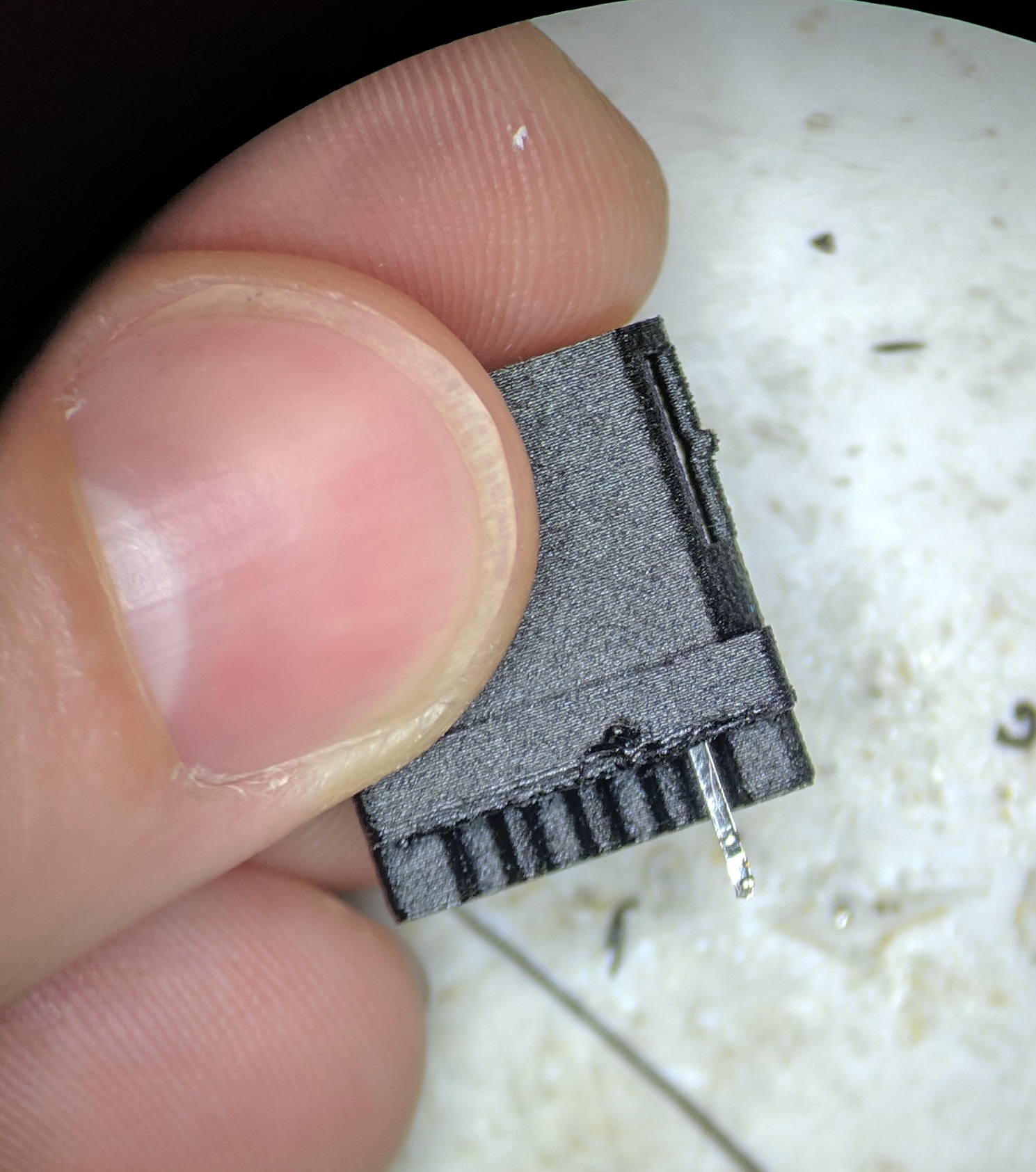
The pins in the VB link cable design are from USB connectors and the center 3D printed Onyx part is specifically designed for Digikey part number 1175-1265-ND. You’ll need 2 USB connectors per VB link cable connector, so 4 USB connectors in total. You’ll need 8 pins per VB connector, or 16 pins total..
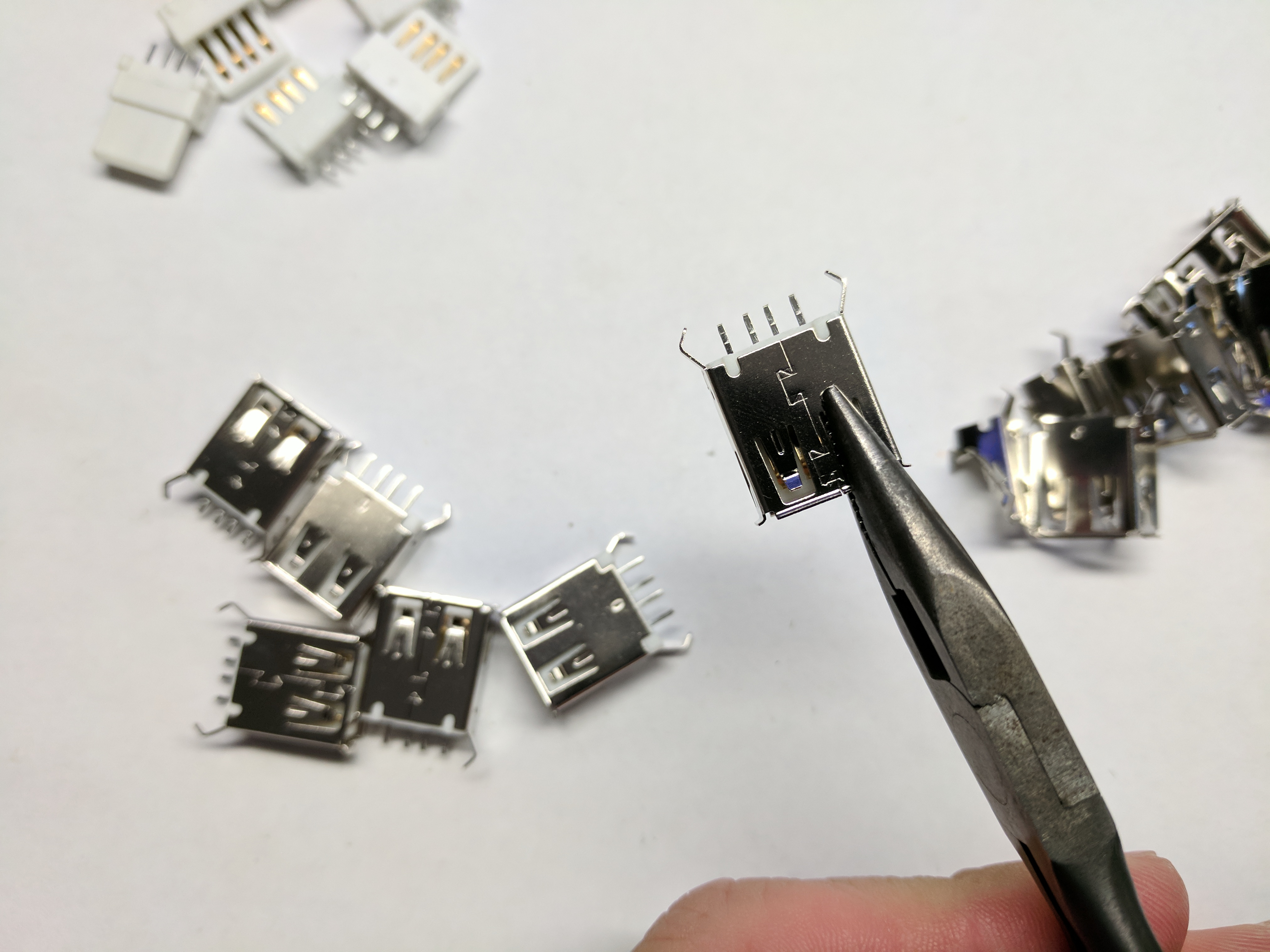
Peel metal cage back |
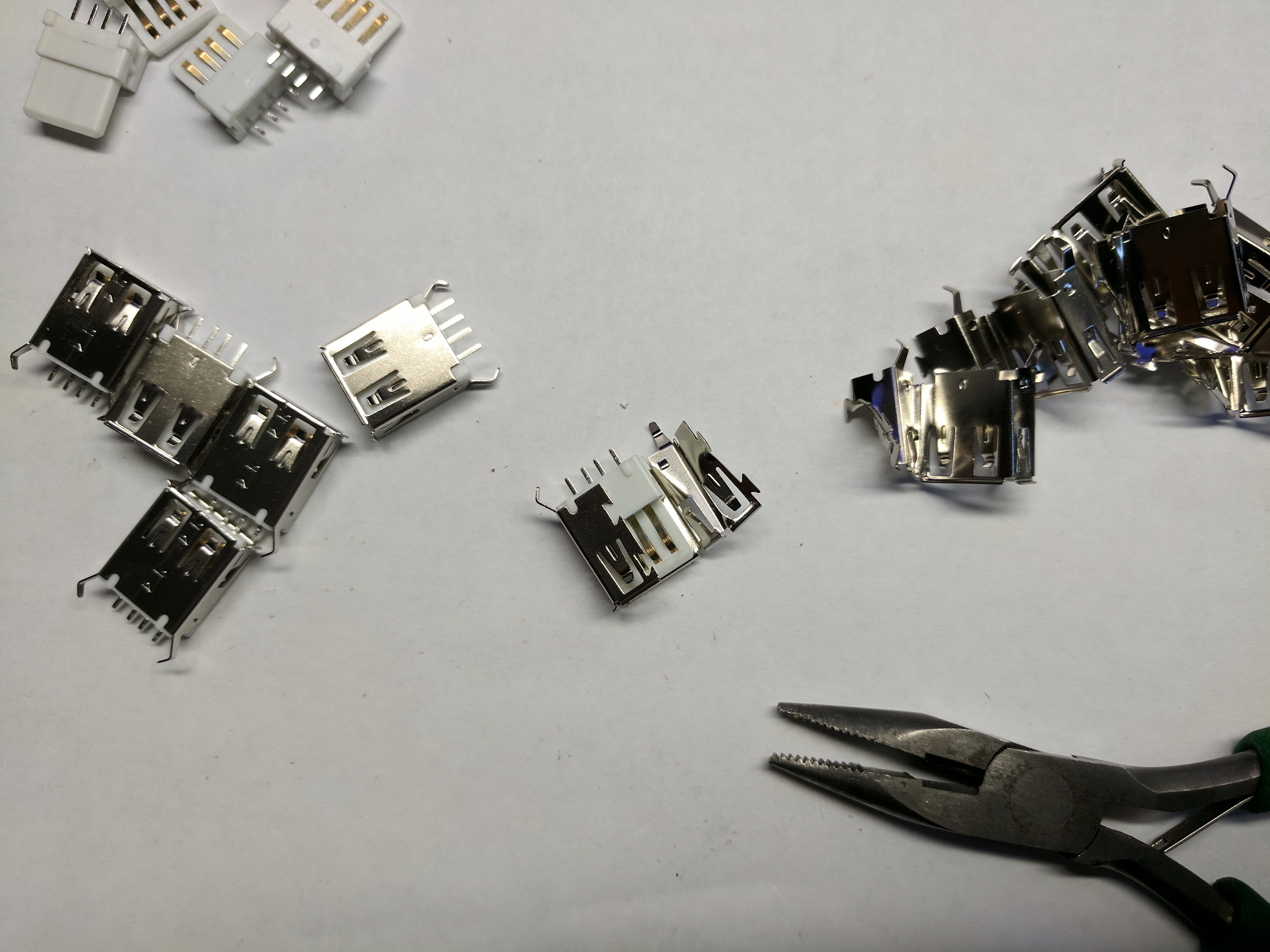
Remove white center with pins |
Take a pair of needle nose pliers and peel back the metal cage on the USB connector. Grab it right at the seem in the cage as shown in the pictures above. Then peel it back until the center white plastic is exposed, which houses the pins. With the cage removed, pull on the 1st pin and a back piece of white plastic will come with it. Remove the pin. Recover the remaining pins as well. Repeat this for 4 USB connectors to acquire 16 pins for a complete cable. You can throw away all the waste metal cages and the white plastic. You only need the metal pins.
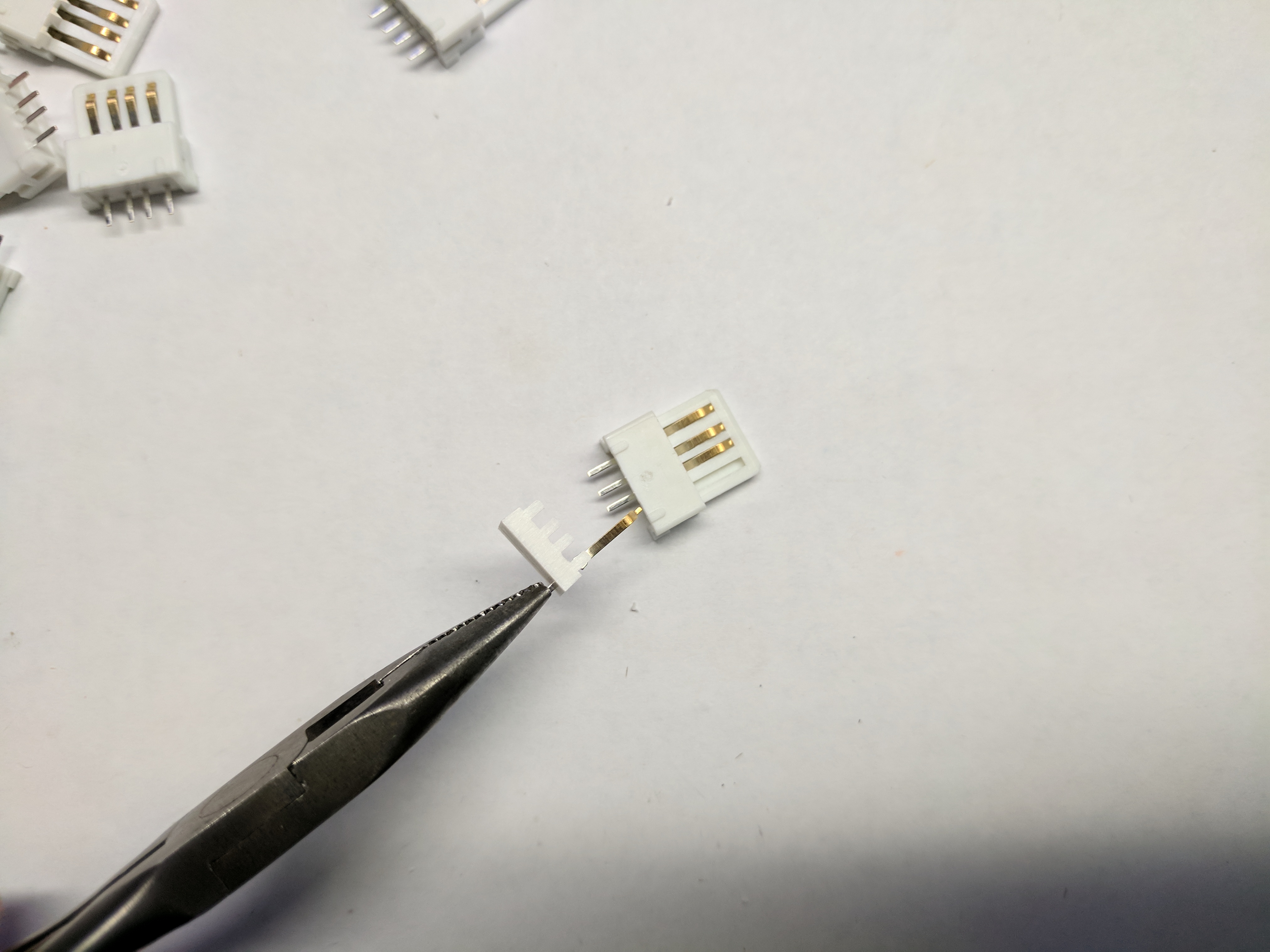
First pin |
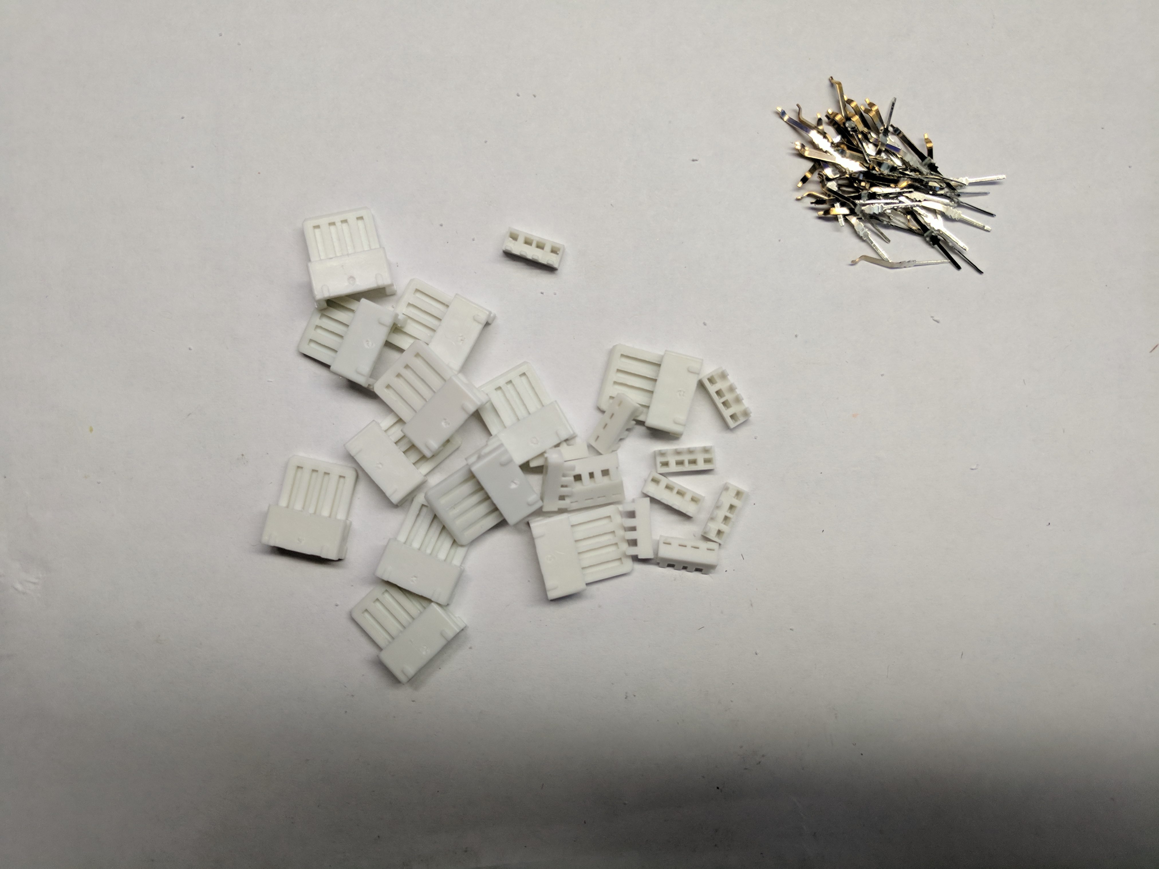
All pins removed |
Inserting USB Pins into Center Connector Housing
This is by far the most time consuming part and will require some patience. The first step is to slide a USB pin in from the front of the center connector so that its back end comes out the back of the center Onyx connector. Then grab the back of the pin and pull it into place using needle nose pliers. You’ll need to pay attention to how far back the front of the pin is on the inside of the connector. You only need enough space from the front of the pin and the housing so that when compressed the pin can move. You don’t want it pushing into the front of the connector plastic. Eye ball it to get the depth correct. The pin should be placed so that the bump in the pin is pointed towards the inside so it can press against the mating connector. This requires some practice. Insert 4 pins for one side first and use your fine tipped tweezers.
Drop pin in from front |
Pull into place via rear |
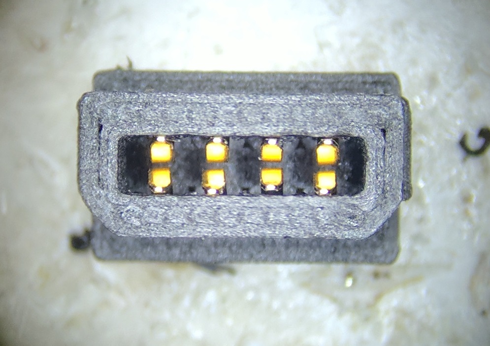
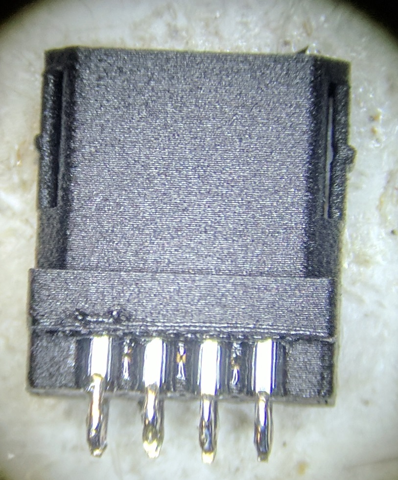
With four pins in one side of the center 3D printed housing, adjust the pin heights so they match close as possible. They shouldn’t be too compressed into the housing, nor floating too high that they’ll hit the mating connector when inserted. This takes some practice and a lot of patience. You may also need to twist them to get them flat. Once you have one side looking good repeat for the other 4 pins. Then adjust those heights as well. When all 8 pins are inserted and looking good then you should see something similar to the picture shown below. Repeat the entire 8 pin process again for the other connector center. You need 2 connector centers per link cable.
Bonding Connector Pins with Epoxy
With two connectors loaded with pins, you’re ready now to start bonding the pins in place. Like I mentioned above, I use a 50mL tube of 3M DP-100 Epoxy and a 50mL dispensing gun. You put the DP100 50mL tube into the gun and remove the cap on the epoxy. Squeeze a bit out so that both sides of the epoxy outputs are primed. Then attach a mixing nozzle. Prep a syringe with dispensing needle and remove the plunger. Then squeeze epoxy in the 50mL gun through the mixing nozzle into the back of the syringe. You don’t need much to bond 16 pins. Once in the syringe move quickly. Place the syringe plunger back in and start applying epoxy to the back of the pins on the rear of the connector housing. Fill in the areas where the pin exits the back of the center 3D printed housing. Do one side of each connector. Then flip over and fill in the rest of the pins. You’ll need to move quickly. Don’t worry about it dripping at this point. Leave some of the pins exposed for soldering at the ends.
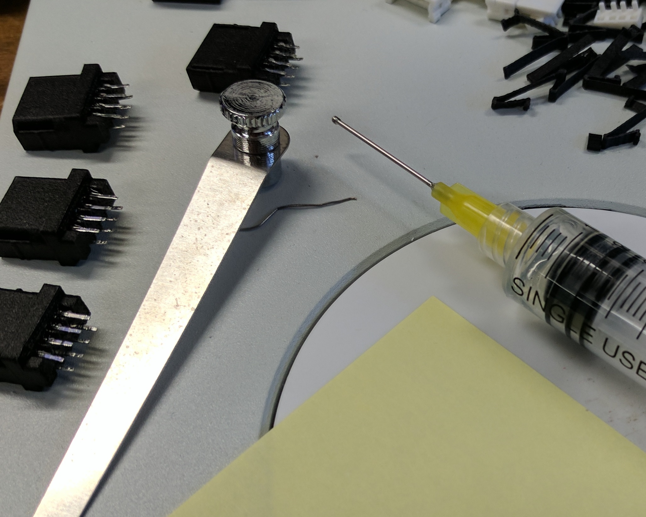
Syringe applying epoxy |
Epoxied pins with tinned tips |
Wait at least 30 minutes for the epoxy to dry. You can continue on to the cable prep below while waiting for the epoxy to dry. It helps to squeeze some out on a piece of paper so you can test for how firm it is rather than messing around with the USB pins. It’s best if you let them dry over night but I’ve built almost all the cables by just waiting 30 minutes. Once they’re dry you can tin the tips of the USB pins with solder to prep them for cable attachment. Do this for both connectors.
Cable Prep
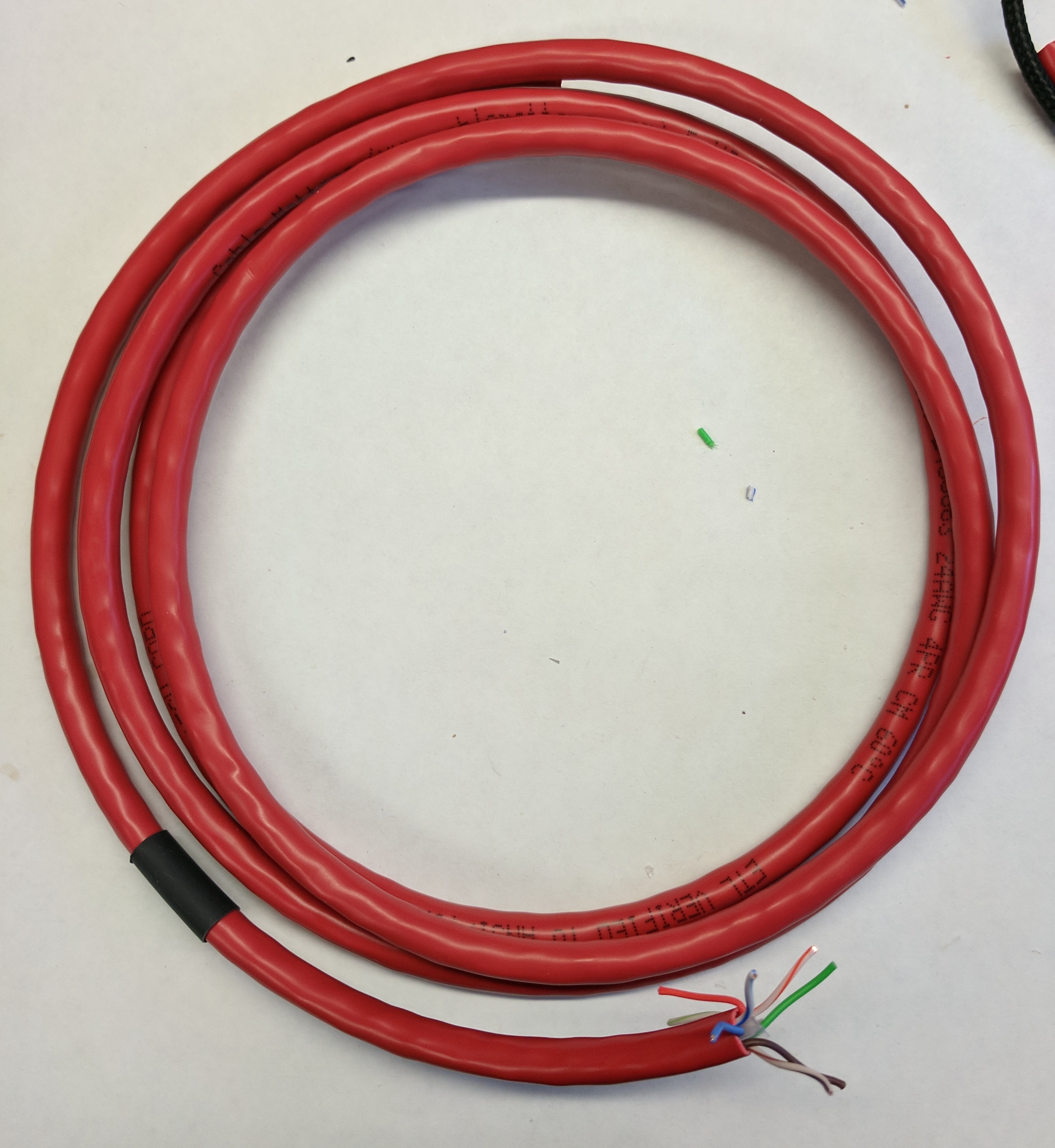
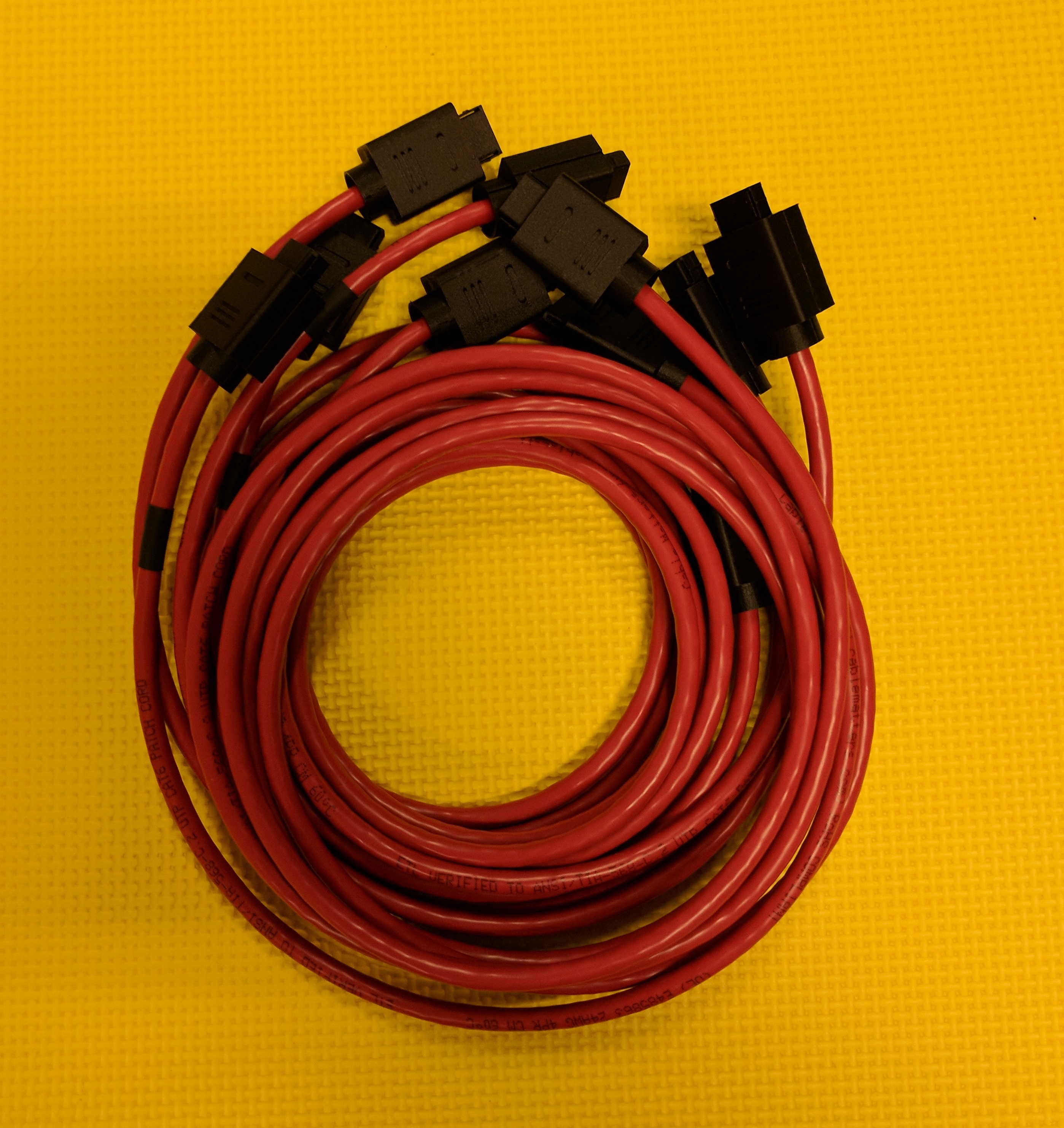
You can prep your red Ethernet cable while waiting for the epoxy to dry above. I use a red Cable Matters Ethernet cable from Amazon.com. I buy 25′ cables to make several link cables. You’ll need 5′ for a single cable. Cut the cable so you have 5′ of bare cable. Then remove about 1″ on each end of the outer red covering to expose the wires. Clip out the support plastic in the middle. This is also a good time to mark one end of the Ethernet cable with heat shrink. Don’t apply heat to the shrink tube yet. We’ll do that later.
Prepped cable end |
Heat shrink marking one end |
Attaching Connectors to Cable
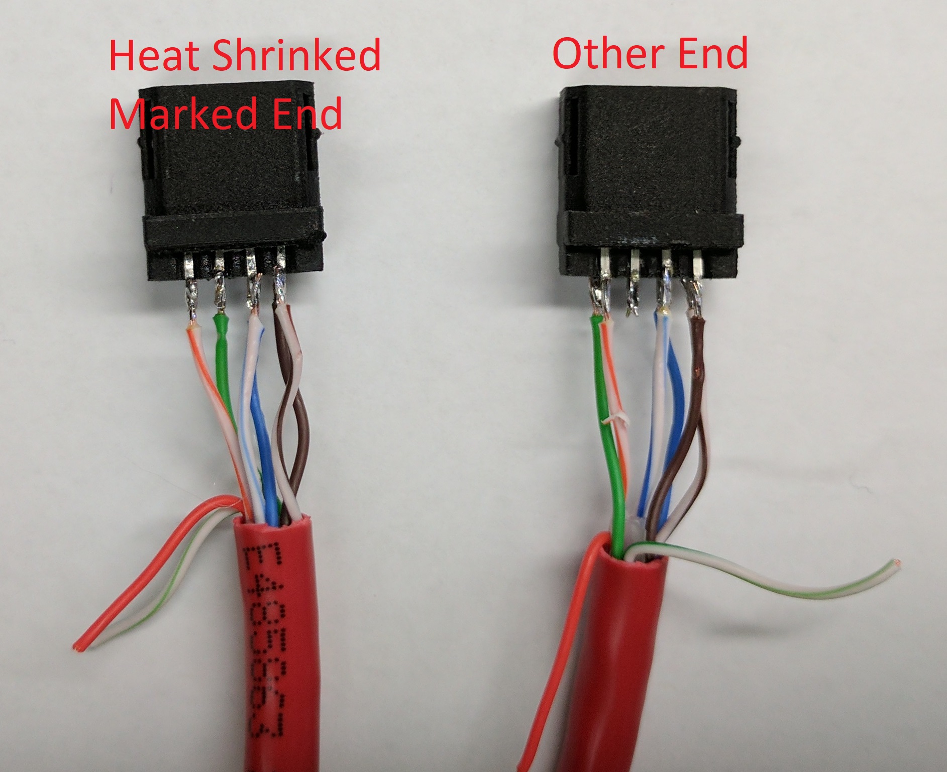
This is how I wire my cables and probably no reason for you not to follow it. We won’t use the solid orange or green striped wires here so I don’t strip or tin them with solder. Review this pictures below several times so they’re clear. It’s a pain to go back and clean it up if you get it wrong and once you bond the covers on, there will be no going back for repairs. When looking at the “Wiring diagram for link cable” diagram, that’s the receptacle that our cable is plugging into. Pay particular attention to the pin numbers and their relationship to the beveled edges on one side of the center housing.
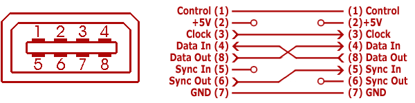
Wiring diagram for link cable |
Ethernet wire coloring scheme |
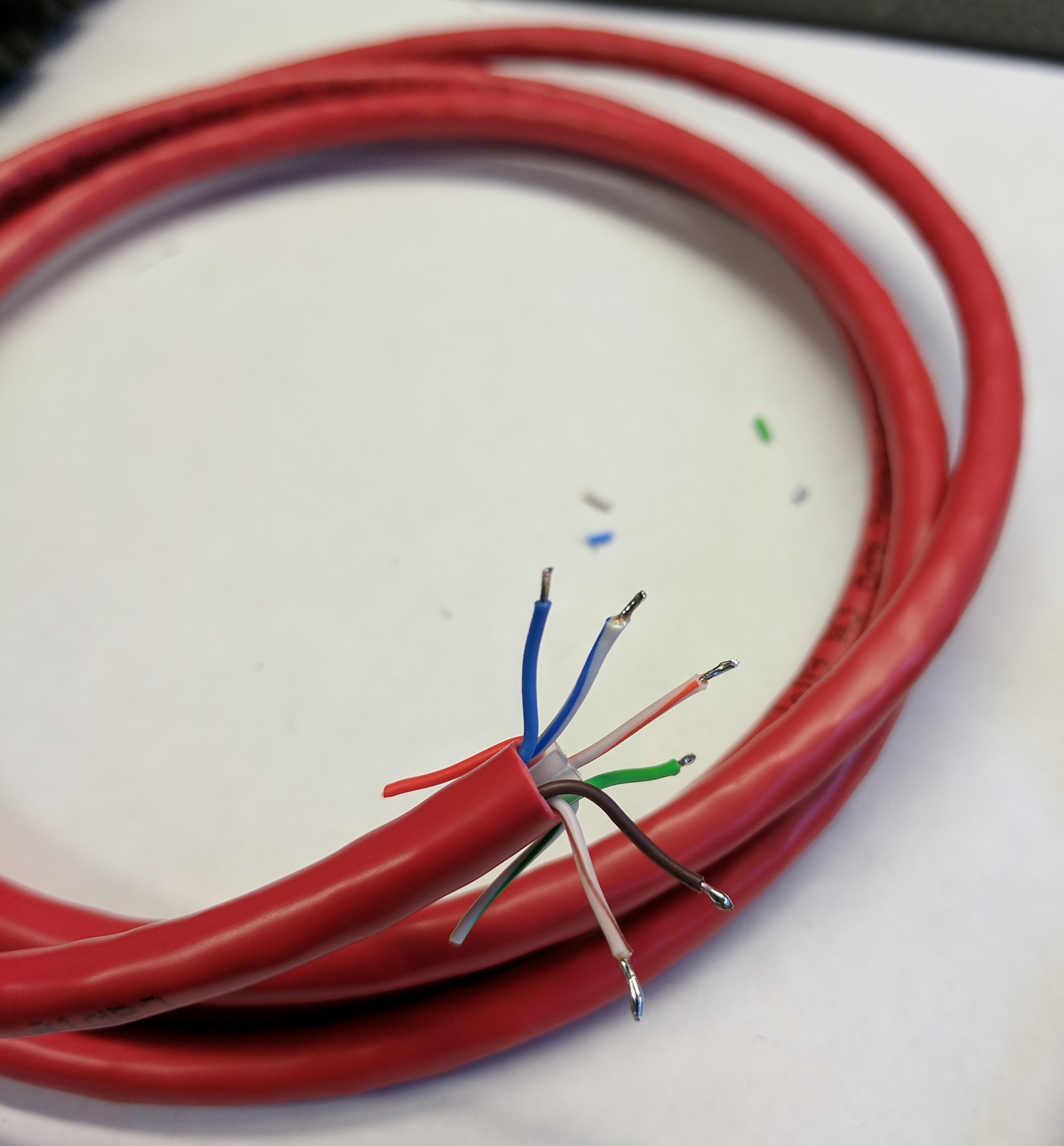
Pin 1 CONTROL will be the stripped orange, Pin 2 is unconnected and that’s why we don’t use the stripped green, Pin 3 is stripped Blue, and Pin 4 is stripped brown. Pin 5 we don’t connect so we skip the solid orange wire, Pin 6 is solid green, Pin 7 solid blue, and Pin 8 solid brown. These are referring to the center 3D printed connector at the end of the cable marked with the heat shrink tube. This also corresponds to the left side of the “Wiring diagram for link cable” picture above. What you should end up with on the cable end marked with the heat shrink is that stripped colors go to pins 1, 3, and 4 with the matching solid colors under those pins on pins 6, 7, and 8. See the picture below. The heat shrink end is on the left. If you then follow the wiring diagram above, you’ll get the solid green wire in a different position (Pin 5) on the other connector along with the brown wires swapped (Pins 4 and 8 swapped). Make sure this is correct!
Solder the wires to the connector correctly and we’re ready to move onto attaching the covers. Now would be a great time to plug the cable into your 2 VB’s and test a game to make sure the cable works. Once we move past this point we start gluing and it won’t be easy to go back.
Retainers and Covers
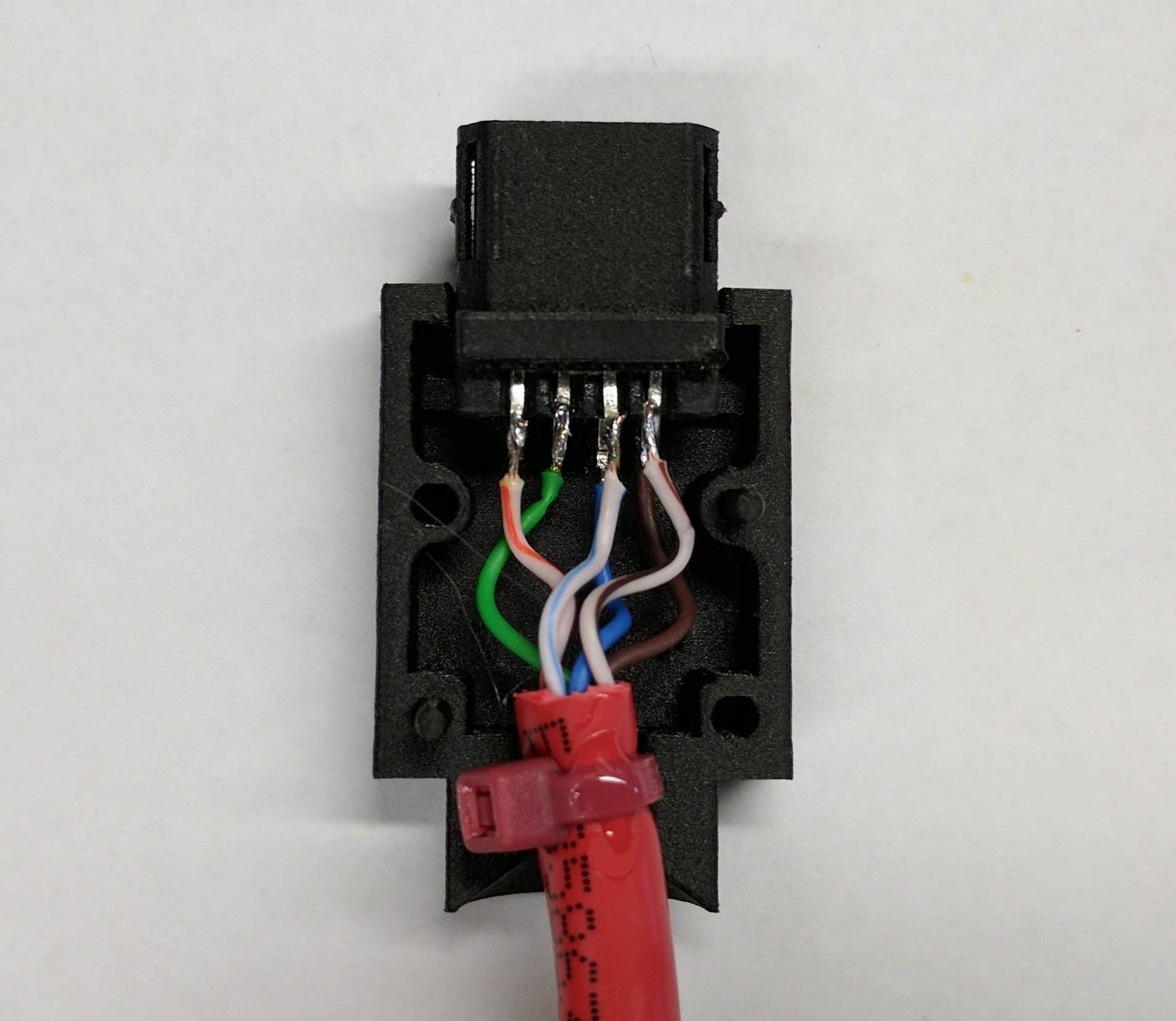
Now we’ll attach some zip ties to the cable ends to help with strain relief. Then we’ll attach the covers. Take the small red zip ties and pull them as tight as you can on both ends of the cables as shown in the picture below. Put a small bead of Loctite 401 on the zip tie where it touches the cable. Let this dry for a few minutes. Clip off any remaining wire that you haven’t used like the solid orange and striped green. Now is a good time for a fit check of the center housing with the covers as well. If you removed any remaining support material like we discussed above, then they should fit snug.
Once both ends have zip ties and the Loctite is dry, then we’re ready to bond on the covers. There’s no turning back here so make sure everything is working and ready. Also, make sure you keep your hands clean of Loctite otherwise you’ll mark up the covers and ruin your nice cable connectors. I don’t pictures of these next steps as the glue sets very quickly and you need to move quickly.
Push the center and cable into one side of a cover and place it flat on the table. The zip tie head will sit very nicely behind the round end of the connector cover and hold the cable in place. Twist the cable if you need to make it fit better. Place a bead of Loctite 401 around its edge as it sits on the table. Orientation is like the picture above. Don’t use too much Loctite 401 otherwise when you put on the mating connector it will ooze out from the side and mar up your connectors. Make sure you have Loctite on the connector pins. Now take the mating cover and press it onto the other cover. Move quickly as the Loctite will start bonding almost instantly. Clamp the two covers together for about 20 seconds. I use my hands against the connectors on the table. After 20 seconds it helps to take another small red zip tie and zip it around the round portion of the covers to hold them together. Repeat for the other connector.
Once the covers are in place and glue is drying go ahead and heat up that shrink tube. Make sure it’s still on the correct end of the cable! Leave the cable alone for at least 30 minutes while the Loctite 401 is really set well. Then clip off the zip ties holding the covers together. Test the cable with two VB’s and you should be good to go!!!
I’ve made a lot of link cables this way. Be careful with the pin placement before bonding and then with the Loctite 401 when gluing things together and you should be good to go. The heat shrink marks the one end of the cable for games who care like TicTacToe or 3D Battlesnake. Other games like Hyper Fighting seem to not care but I almost always make Player 1 the heat shrink marked end of the cable. Everything should work fine if you follow that.
Have fun!
