 Mellott's VR
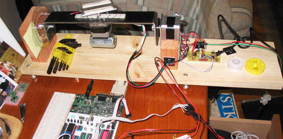
3DOF Tracker
December 2008
This is my first 3DOF Tracker project. I’m continually working on it to try to improve the performance. It has come out quite nicely so far. This first design uses a tri-axis magnetic sensor along with a tri-axis accelerometer to compute yaw, pitch, and roll. It’s all done on an Atmel atmega16 running at 7.32Mhz. One of the challenges in this project was to see if the atmega16 could handle such a task at the speed I wanted. Although on the edge of what it can handle speed-wise, it turns out it can handle this project quite nicely.
In the image above the actual sensors for the tracker reside on the white breadboard. To the left of the breadboard is the STK500 Atmel programming board I’m using for development. Behind that is a 2DOF calibration table that I built to measure the accuracy of the tracker. The calibration table is being controlled by a atmega163 board that I designed for the VFX1 Linkbox project. Overall I’ve spent probably hundreds of hours researching and building this project. It’s by far my most advanced to date and the funny thing is once I figured out how to do it, it’s actually not that complicated.
In the tradition of my other projects, I’m going to list the documents you need to read to understand how the tracker works and my micro-controller code. I won’t give a step by step because that would just take too much time. This really isn’t a “step-by-step” type of project anyway. It takes some serious time in reading and understanding the material but like I said above, once you understand what’s going on, it’s not that complicated.
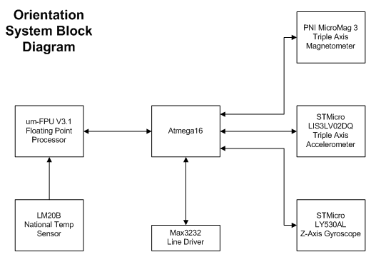
This project is a 3DOF tracker built using a MicroMag3 tri-axis magnetic sensor from PNI, an STMicro LIS3LV02DQ accelerometer, and an atmega16 running at 7.32Mhz. The sensors are running on the SPI bus of the atmega. This makes the interface really easy to deal with. Both sensors are fully digital and accessible over the SPI bus. You can find more information about them via their data sheets. In the image above you can see a 16DIP with a white label. This is a uM-FPU V3.1 floating point processor. It’s supposed to give a speed up of 2 to 4 times when doing floating point calculations. It also runs on the SPI bus. I haven’t implemented it as part of the tracker yet, but eventually I will. Even though the atmega gives the speed I designed for, I’m interested in how this processor can speed things up. It reduces the clock cycles needed for floating point calculations by quite a bit.
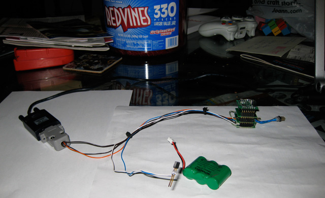
The cal table consists of two PK244M-03AA Vexta motors from Oriental Motors, two EasyDriver motor drivers from Sparkfun.com, an atmega163 controller board built by myself, and a smattering of wood and steel. It’s powered by a 24V 4A supply, although it only draws about an amp or so. The motors are actually right on the edge of what they can handle as far as torque. If you build one, I would recommend the next size motor. That’s why you see the large bolt at the bottom of the middle motor for weight balancing. This is partly due to a slight design error, hahahaha. But even with this balancing the motor can just turn the steel bar when the bread board is attached. Any additional load and the motor skips. Originally I built it using an aluminum plate but couldn’t find the aluminum collar shafts to weld to it. I may do this in the future as my ME room mate has made some aluminum collar shafts for me. To get a sense of dimension, the steel plate is 10 inches long and 2 inches wide. Otherwise the dimensions aren’t important, just build whatever works for you.
The heart of this project is in the software. It’s all programming. The code for the tracker (atmega16) is here. The code for the calibration table (atmega163) is here. The heart of the tracker code is in the sensor control and the angle calculations. I won’t explain them here cause frankly it took me a long time to get a handle on it, but there are a few particular app notes on the web that you should look at. These are in addition to the datasheets for the sensors.
The app notes are:
Accelerometer
- Freescale Semiconductor App Note AN3461. “Tilt Sensing Using Linear Accelerometers”, by Kimberly Tuck.
- Freescale Semiconductor App Note AN3107. “Measuring Tilt with Low-g Accelerometers”, by Michelle Clifford and Leticia Gomez.
- Kionix App Note AN012. “Accelerometer Errors”, by un-named author.
- IEEE Sensors Journal, Vol. 6, No. 6, December 2006. “Sensing Tilt With MEMS Accelerometers”, by Sergiuz Luczak, Waldemar Oleksiuk, and Maciej Bodnicki.
Magnetometer
- Honeywell, SSEC. “Applications of Magnetic Sensors for Low Cost Compass Systems”, by Michael J. Caruso.
- PNI App Note 1001766 R01. “Application Note: Multipoint Calibration Primer”, by un-named author.
- “A Calibration Technique for a Two-Axis Magnetic Compass in Telematics Devices”, by Seong Yun Cho and Chan Gook Park.
- Honeywell Inc. “Applications of Magnetoresistive Sensors in Navigation Systems”, by Michael J. Caruso.
In addition to these there are several forum conversations on Sparkfun.com that go over using these sensors and their corresponding calculations.
The calibration table is merely a measurement device and you can see the mention of its design on the IEEE paper listed above. Using this requires some basic understanding of stepper motors and a few simple micro-controller operations. I think the micro-controller code will speak for itself. I had no idea how to use a stepper motor before this and thats why the Easydrivers from Sparkfun.com are so beautiful. You only need to tell it what direction and give it a pulse to move the stepper motors. So really I have a basic understanding of the internal operations of the motors and drivers but that’s about it. I let the hardware handle the details because the stepper motor control wasn’t the point of this project. Although it did turn out to be quite interesting.
I have a master zip file containing all the documentation and code I used for this project but its a 160Mbyte file and geocities doesn’t like it. I also have a 60Mbyte or so zip file of several video’s showing the tracker and calibration table in action. I’ll post them to YouTube or something similar in the future. Anyway, I think that gives you an idea about getting started. Really all the work and understanding is in those application notes/data sheets. With the implementation in code I’ve given, I think anyone capable can figure it out. You’ll find calibrating the tracker is where you’ll spend most of your time. As always, email if you have questions. As I progress more on this project I’ll update this page. Have fun!!
Update: I now have all the calculations being done on a uM-FPU V3.1 floating point processor and the difference is amazing. The tracking data is smoking now!! I’m getting calibrated and corrected updates of Yaw, Pitch, and Roll at a designed rate of 100Hz. The update rate before the FPU was 20-40Hz. I set the sensors for an update rate of 160Hz so 100 is in the ballpark with all the signal processing going on in the background. It is possible to update faster but it requires setting the MicroMag3 to a higher update rate, which is less accurate and has more noise. I’ve decided the PS128 setting I’m using now is a good compromise. The accelometer can send data at a rate of up to 2.5kHz, so that’s not the limiting case. The overall performance of the system is set by the MicroMag3. I’m extremely happy with how this project turned out. I’ll update more information as I have time. My next step is to design PCB’s so the entire system resides in a 1″ cube enclosure. Sweet!!
Update: 7/30/2008 I’m running the tracker on a 11.0592Mhz crystal now. That’s a bit outside of the 8Mhz spec limit of the atmega16l but its working nicely. Right in the middle of the PCB design. I’m aiming for roughly a 1″ cube for a final package size. The MicroMag3 will stack on top of 2 other boards. The first board containing the atmega16L, floating point processor, temp sensor, and accelerometer. The second board containing a voltage regulator, the max3232 line driver, and the RS232 connector (probably in the form of some type of RJ45 jack). These three boards will stack to form the tracker, using the header pins as a bus between the boards. I’ve already built the libraries I need in Eagle Cad. As soon as the summer semester is over I should be able to have the first PCB’s made.
Update: 8/29/2008 I’m currently having the boards made. Three of them. A digital board, MEMs board, and a Communication board. All 1″ square. I’m getting pitch and roll angles that have an accuracy of within 0.5 degrees. Most of the error in probably in my measurement and not the actual sensor. The Yaw angle I’m having a harder time measuring. From manual measurements I have as large as 5 degree error with the average being around 1.5-2 degrees. The noise alone of the Yaw heading is about 1 degree. In my PCB design I’ve added an STMicro LISY300AL 3.3V gyroscope. I’m hoping that with the gyro, in conjunction with the MicroMag3, I can get a sub degree accurate heading. For most of my applications I don’t necessarily need a very accurate heading but I’d like to be able to use this tracker for anything from VR trackers to unmanned vehicles. I’ll be coupling this orientation 3DOF tracker with a positional RF tracker to attempt to achieve a 6DOF tracker that can locate an object in 3D space as well as it’s orientation. My idea at this point is that I can plug this 3DOF tracker into any other system I design to achieve a 6DOF configuration. My next project will be to couple this system to an ultrasonic tracker.
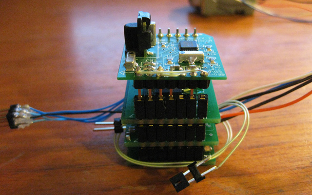
Update: 11/14/2008 I’ve built the PCB version. The current size is 1″x1″x2″. I want to reduce the height so I’m looking for a better header system. I want the cube to remain configurable so I don’t want to soldier all the boards together. You can see the picture below. After Mid-terms and finals, hopefully I’ll be able to work on it again. With a very rough calibration I can get the same specs as the breadboard version of about 1 degree Yaw noise and 0.2 degree of Accel noise. There is still lots of work to be done to improve the system performance.
Update: 12/17/2008 I’ve updated the Atmega16 file download above with the latest code for the floating point processor. I didn’t update the TrackerTable cause the changes aren’t significantly different and you can only really use it if you build the same table. The only difference is now the Matlab code is greatly simplified cause it doesn’t do the orientation calculations.
I have an end of the semester presentation on the project but unfortunately the file size is too large and Geocities won’t let me upload it. Maybe I can remove the videos and upload that. It gives a general view of the project and what I built. If anyone is interested just email me and I send you a copy through ftp or something similar. That will most likely be it on this project for a while. It’s the end of the semester and I’m burnt out. Some videos of the prototype system below.
The design specs on the first PCB version:
3.3V , Configurable Sensor System on an SPI bus.
Design goal of 1″x1″x1″ Cube (Currently 1″x1″x2″)
Atmega16/32 @ 11.059Mhz (atmel.com)
Floating point processor uM-FPU V3.1 (Micromega.com)
PNI MicroMag3 Triple Axis Magnetometer (PNI.com)
ST Micro LIS3L02DQ Triple Axis Accelerometer (stmicro.com)
STMicro LY530AL Z-axis Gyroscope
National LM20B Temperature Sensor (national.com)
3.3V voltage regulator
Max232 line driver
100Hz update rate, 1 degree Pitch and Roll, 5 degree Yaw (Hoping to improve this with the aid of the gyro sensor)
Sensor boards can be added or removed from system depending on required configuration.
