|
|
|

Material needed:
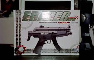
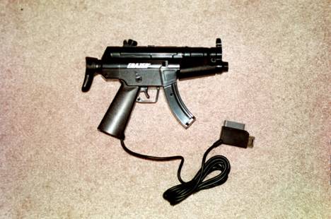
- Erazor MP5 Light Gun. http://www.gocybershop.ca/product_details.asp?ID=410
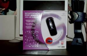
- Ultra Cordless USB Gyromouse. www.gyration.com
- Radio Shack 7x5x3 Enclosure Part # 270-1807
- Radio Shack Pushbuttons Part # 275-609
- Standard PS2 Keyboard
- 25ft DB25 M/M Serial Cable
- DB25 socket and mounting hardware
- 1- red LED and clip
- 1- green LED and clip
- Plastic stick-on Standoffs http://www.mouser.com Part # 561-LAD500 1/2” long
- 0.22uF SMD 0805 capacitors http://www.mouser.com Part# 81-grm40x224k16d
- Snap on RF Choke
- Ferrite RF Choke
- Lots of wire
- Shrink tube
- Rubber feet
- Solder
|
|
|
Tools needed:
- Soldering Iron
- Hot Glue Gun
- Basic hand tools (i.e., pliers, screwdrivers, etc)
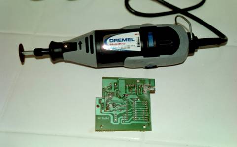
- Dremel with grinding wheel
- Drill with bits
- DVM
- O-scope (for troubleshooting)
- Wire cutters
- Wire strippers
Recommended Sequence of Steps for VR Gun build:
- Purchase material
- De-trash MP5 gun
- Clean PCB in MP5 gun
- Clean gun
- De-trash keyboard
- Decode keyboard card
- Wire keyboard card and DB25 cable
- Wire keyboard card and PCB buttons and switch
- Wire trigger and tracking activate switch
- Build Enclosure
- De-trash gyromouse
- Wire MG100 into Gun
- Wire and mount MG100 PCB into enclosure
- De-trash gyromouse receiver and mount into enclosure
- Reassemble enclosure and gun
This is not a simple project. Unless you are very experienced with soldering and or an electronic technician, you may want to read this procedure before beginning. Here are some basic electronic questions. If you can answer these truthfully without having to look it up then you probably capable of building a VR Gun.
- Do you know what ‘tinning’ wires means?
- Can you use a DVM?
- Can you use an O-Scope?
- Do you know what solder wick is?
- Are you familiar with the concepts of voltage and current?
- Are you mechanically inclined?
If you can answer most of these questions then you’re probably in good shape. This document will lay out a VR Gun build. It is meant as a guide and a reference. It may not contain every detailed step but will definitely show you the path.
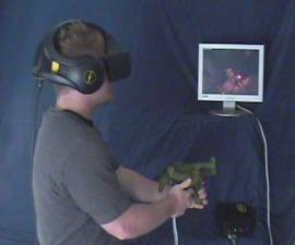
The approximate cost for building the VR Gun USB is 150.00 USD. You will need 10 to 15 hours to build one unit. The VR Gun will provide you with a tracked game controller designed for FPS games. It is designed to be used with an HMD and will provide you with a level of immersion unseen in prior devices.
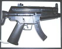
Step 1. De-trash Blaze MP5 Erazor Gun
- You’ll need a small Phillips screwdriver and a pair of wire cutters.
- Remove all screws from the MP5 Gun and open it up. There are approx. 12 screws.
- Once open, remove everything except the PCB (printed circuit board) and the trigger switch. Cut all wires and remove all cables. Remove the feedback motor and mechanism.
Step 2. Clean PCB in MP5 Gun
- Remove the PCB from the gun by removing the four small black screws with a small Phillips screwdriver
- Using your wire cutters, cut everything from the board except the switches and or buttons. Remove all resistors, capacitors, IC’s and connectors.
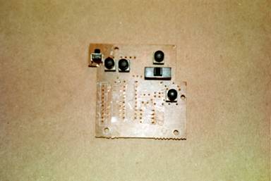
- Use a DVM to identify all switches and button trace paths.
- Determine which pins are connected and activated by each switch and or buttons.
- Isolate each of these switches or buttons by cutting the trace paths as to disconnect it from the rest of the circuitry. Each switch and or button must be COMPLETELY isolated or problems will occur when wiring the keyboard card. Use a dremel and grinding wheel to remove the traces where needed.
- Reinstall PCB into the gun.
Step 3. Clean the Gun
- Clean the gun of all cut materials
- Wipe all grease from the plastic body. It must be completely clean so plastic stick-on stand offs can be attached.
Step 4. De-trash Keyboard
- Remove all screws from the keyboard and pull apart.
- Remove the keyboard card along with the PS2 cable.
- Throw away the rest of the keyboard. Only the keyboard card with its attached cable will be needed.
- On one side of the keyboard card you will see lots of contacts at the bottom edge of the card. They will be covered in carbon. Scratch this carbon off with a screwdriver. Use a pencil eraser to remove the last bits of carbon until you can see nice shiny copper contacts. All carbon needs to be removed so they can be soldered.
Step 5. Decode Keyboard card
- You will need to decode your keyboard card. To do this you’ll need a jumper wire with alligator clips.
- Plug your keyboard card into your computers PS2 keyboard port.
- Open any text editor such as Notepad.exe.
- Using the jumper wire start connecting the contacts together two at a time.
- Record any letters or numbers that are generated and what contacts generated them.
- You will need 6 total numbers and or letters for the gun. These numbers or letters will be wired to the guns switches and buttons to provide response to the computer while playing games.
Step 6.
- Cut the PS2 cable from the keyboard card. Take note of which color wire goes where. Record this for future reference. Do not throw away the keyboard cable. It will be used later.
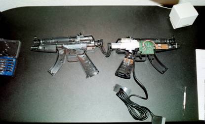
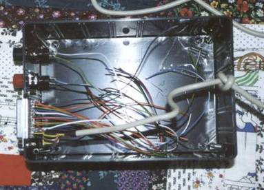
- Fit the keyboard card into the gun. Mount it to the piece that does not house the PCB with the buttons and switches. Mount it in the rear as seen in the picture.
- You will have to trim the internal plastic of the gun to make it fit properly.
- Mount
the keyboard card into the gun using plastic stick-on standoffs.
- Remove all solder from the solder pads where the keyboard cable was cut. Use solder wick to remove everything so that holes are apparent.
- Tin
all the keyboard contacts.
Step 7. Wire
keyboard card and DB25 cable
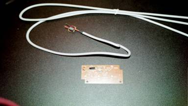
- Take your 25 foot DB25 M/M serial cable and fold it in half.
- Cut it in half. One half will be used for the gun. You should have a cable approximately 12 or so feet long with a DB25 male connection on one end. The other half will not be used.
- Remove
the outer coating of the cable approximately 1 foot.
- We will be using pins 1 thru 11 and 21 thru 25 for our gun.
- Use the DVM and ohm out the pins and wires. Take note of which color wire goes with what pin.
- There is a bare shield wire coming out of the DB25 cable. Solder this wire to the base of the PIN 25 wire.
- Remove a small portion at the base of the DB25 pin 25 wire and wrap the bare shield wire around it. Solder into place.
- The pin 25 wire will also connect to the keyboard card solder pad 5. Cover the connection with electrical tape.
- Cut any unused wires short. The wires for DB25 pins 12 thru 20 will not be used.
- Drill a hole the same size of the DB25 cable in the bottom door of the gun to allow the cable to pass. It should be approximately a 5/16 hole depending on your cable.
- Before drilling remove the metal plates on the inside of the bottom door of the gun.
- Stick the cable in approximately 3” past the outer coating and place a zip tie at the base to keep it from pulling out.
- Route the DB25 pin 21 thru 25 wires up to the keyboard card cable solder pads (where the PS2 cable was cut from).
- Solder the DB25 pin 21 thru 25 wires to the pads accordingly.
DB25 pin Wires to Keyboard card pads
DB25 pin wire 21 to keyboard card solder pad 1.
DB25 pin wire 22 to keyboard card solder pad 2.
DB25 pin wire 23 to keyboard card solder pad 3.
DB25 pin wire 24 to keyboard card solder pad 4.
DB25 pin wire 25 to keyboard card solder pad 5.
This essentially makes the DB25 cable an extension for the PS2 cable which will be reconnected in the enclosure at the DB25 connection.
Step 8. Wire keyboard card and PCB buttons and switch
- You’ll need 11 wires to solder the guns PCB buttons and switch to the keyboard card. What you are doing is soldering these buttons and switch to the card to generate the numbers and letters you recorded earlier. You are replacing your keyboard keys with these buttons and switch. Thus making a small keyboard.
- Connect the wires from your recorded contacts to the buttons as necessary.
- Do NOT connect any keyboard wires to the main trigger or the ON/OFF push button. Wire only to the thumb trigger, the switch, and the momentary push buttons.
- Use
two numbers or letters that had one similar contact in ‘common’ for the
switch. The switch will have three
connections. A ‘common’ connection
to the center top pin and the two other contacts on the outer top
pins. This should generate one
letter when the switch is in the forward position, one letter when in the
back position, and NO letters when in the middle position. This switch is perfect for enabling
mouse look in games.
Step 9. Wire trigger and tracking activate switch
- Solder the DB25 pin 9 wire to the top tab of the main trigger switch, along with a jumper wire from the top tab to one side of the ON/OFF push button the gun PCB.
NOTE: There is only one ON/OFF Push button on the gun PCB. This is used to turn the tracking on and off.
- Solder the DB25 pin 11 wire to the other side of the ON/OFF push button switch of the gun PCB.
- Solder
the DB25 pin 10 wire to the middle tab of the trigger.
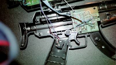
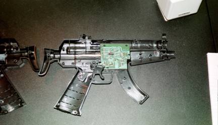
- Route
the wires as shown in the picture.
- Set the gun portion aside for now.
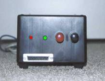
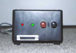
Step 10. Build Enclosure
- Solder long leads (wire-approx 6” long) to one green LED and one red LED.
- Also solder long leads to the red radio shack push button and the black radio shack push button. Use shrink tube where appropriate.
- Cut an opening in the bottom left edge of one of the small sides of the enclosure for the DB25 socket to be placed.
- Once the cut is in the enclosure hold the DB25 socket into place to use it as a guide to drill your mounting holes.
- Drill the mounting holes. Do not mount the DB25 yet.
- Solder wires approximately 6” long each to pins 1 thru 11 on the DB25 socket. You should have 11 wires total with one end soldered to each pin.
- You need to solder 0.22uF surface mount caps between pins 1 & 14, 2 & 15, 5 &17, and 6 & 19.
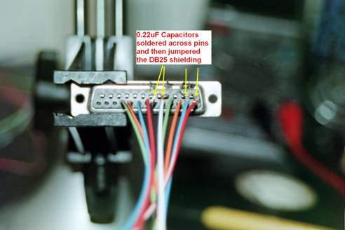
- Now solder pins 14, 15, 17, and 19 to the outer casing of the DB25 socket using small jumper wires. This outer casing will later be soldered to ground. PIC 6
- Drill ¼” holes for both LED’s and ½ holes for both buttons.
- Drill the first LED hole (1/4”) 1” from the left and 1.5” from the bottom edge of the enclosure. The next hole will be for another LED 2” from the left and 1.5” from the bottom.
- Your two button holes (1/2”) will be placed at 3” and 4” from the left and 1.5” from the bottom.
- Once drilled, the red LED goes in the left most hole. The green LED in the next LED hole.
- The red radio shack push button mounts in the hole closest to the LED’s. The black radio shack push button mounts in the remaining hole.
NOTE: You will need ¼” LED clips to mount them into the holes you drilled.
- Now
solder the keyboard cable you removed earlier to the DB25 socket. Refer to your notes on which color went
to what pin. Remember: DB25 pin 21
goes to keyboard card wire 1, DB25 pin 22 goes to keyboard card wire 2,
and so on.
- Now connect the gun to the enclosure.
- Connect the keyboard cable to a keyboard port on your PC. Open up any text editor and test your buttons. You should get output from all of them except the main trigger and the ON/OFF push button. If not, check your wiring. Insure each button or switch is isolated from the rest of the circuit.
Step 11. De-trash Gyromouse
- Remove the gyromouse battery.
- Remove the two screws in the battery compartment.
- Pop the left/right click buttons off.
- Remove any revealed screws.
- Remove the top plastic frame of the mouse.
- Remove any revealed screws.
- The gyromouse PCB’s should now be removed from its plastic enclosure.
- Remove
the thumb wheel.
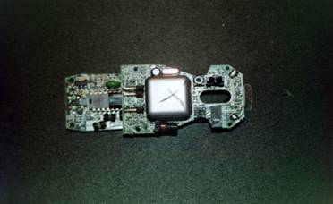
- You should now see the MG100. It’s a square metal canister.
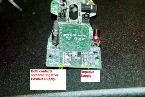
- Cut the contacts off on the left side of the MG100. They are long metal tabs sticking up along the side will black tape behind them on the MG100. The two contacts closest together will be soldered together later and will make the positive supply connection. The other contact farther from the two will make the negative supply connection.
- Separate the two PCB’s. They are connected by a pin header.
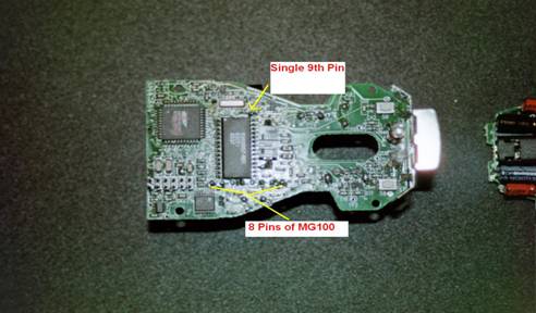
- Take the PCB with the MG100. Flip it over. On the bottom there will be 8 pins along one side of the MG100 and 1 pin on the other side. You may have to look at the PCB for awhile to become familiar with the appropriate pins. The pins you are looking for are on the OPPOSITE side of the PCB’s MG100.
- Before removing the MG100 from the PCB mark it for orientation such as front, back, left, and right.
- You
need to remove all solder from these 9 pins with solder wick so the MG100
can be removed from the PCB.
NOTE: BE EXTREMELY CAREFUL NOT TO DAMAGE THE MG100
OR THE TRACES ON THE BOARD. IF DAMAGED,
THE VRGUN AND GYROMOUSE WILL BE UNUSABLE.
Step 12. Wire
MG100 into gun
- Once the MG100 is removed, solder it in the gun. You will need to solder DB25 cable wire PIN 1 thru 8 to the side of the MG100 with 8 pins. The single pin on the opposite side is not used. Solder DB25 pin wire 1 to MG100 pin 1, pin 2 to 2, and so on and so forth. Do this until you have all eight wires soldered to the MG100.
Step 13. Wire and mount MG100 PCB into enclosure
- On the back side of the PCB that once housed the MG100 you will need to remove R38 and R41. They are near the front of the board near the antenna. Removing these resistors will disable the optical tracking portion of the PCB.
- There where three contacts that you cut earlier. The two that are closest together should now be bridged with solder to make them one big contact. This is the positive supply connection. The third contact to the right of the pair will be the negative (or ground) supply connection.
- Solder long leads (approx. 1’ wires) to the positive supply connection and another to the negative supply connection.
- The PCB that housed the MG100 will now be connected to the DB25 socket inside the enclosure. Solder the DB25 socket wires 1 thru 8 to the holes in the PCB where the MG100 pins 1 thru 8 were soldered. 1 goes to 1, 2 goes to 2, and so on.
- Ohm out the activate button (this is the button that enables the gyromouse tracking when in the air. Refer to the gyromouse manual to locate the relative position of this button) and the left click button on the PCB that housed the MG100. These two buttons should have a common connection. Find this common connection and solder it to the DB25 socket pin 9 wire.
- Solder DB25 pin 10 wire to the other side of the left click button.
- Solder DB25 pin 11 wire to the other side of the activate button.
- Solder a wire from the DB25 socket outer chassis to the negative supply connection on the previously housed MG100 PCB.
- Solder the leads from the enclosure black radio shack button across the ‘teach’ button contacts (refer to the gyromouse manual for the relative position of the teach button).
- Solder the green LED leads to the small LED on the PCB that previously housed the MG100.
- Now reconnect the two PCB’s at the pin header. Secure them in together with a zip tie.
- Now position the PCB into the enclosure close to the front of the enclosure (the DB25 socket side).
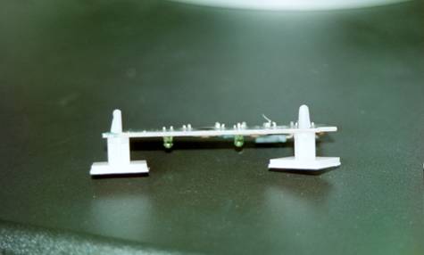
- Set two plastic stick-on standoffs on either side of the PCB. Glue the PCB in place to the standoffs. Allow the glue to dry before continuing.
- Zip tie the commons wires together to clean it up. LED and switch leads can be zip tied together.
- Place a snap on RF choke around all eight MG100 wires from the DB25 socket to the PCB.
- Feed
a ferrite choke around the positive and negative supply connection wires.
Step 14.
De-trash gyromouse receiver and mount into enclosure
- Remove all rubber feet from the receiver.
- Remove all revealed screws.
- Remove PCB from plastic enclosure.
- Remove antenna.
- Solder positive and negative supply connection leads from the PCB that housed the MG100 to the USB supply pins of the receiver.
- Mount receiver PCB into the main enclosure along with the PCB that previously housed the MG100. Use stick-on standoffs to hold in place. Secure it with hot glue gun.
- Solder red LED leads to the receivers small green LED.
- Solder
the red radio shack push button leads across the ‘learn’ button on the
receiver (refer to the gyromouse manual for relative position of this
switch).
At this point you should plug in the USB and keyboard port and test everything before buttoning it up.
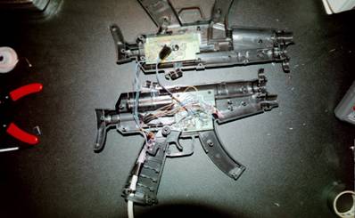
- Glue
the MG100 sensor into the VR Gun with the hot glue gun. Make sure the front of the sensor is
facing the barrel and the back of the sensor is facing the guns button and
switch PCB. Refer to the picture
below for relative position. You
may have to trim some internal gun plastic to make it fit.
Step 15. Reassemble enclosure and gun
- Carefully put the gun back together. Pay attention not to pinch any wires.
- Drill holes along the edge of the enclosure and its lid so that the keyboard cable and USB cable can come out of the rear.
- Place the enclosure lid on.
- Put rubber feet on the lid.
YOUR DONE!!!
|
|
|